Continue to Site

Eng-Tips is the largest engineering community on the Internet

Intelligent Work Forums for Engineering Professionals

  • Congratulations cowski on being selected by the Eng-Tips community for having the most helpful posts in the forums last week. Way to Go!

Pin connection for RC beam 2

Status
Not open for further replies.

NewbieInSE

Structural
Dec 19, 2019
234
Hello all,
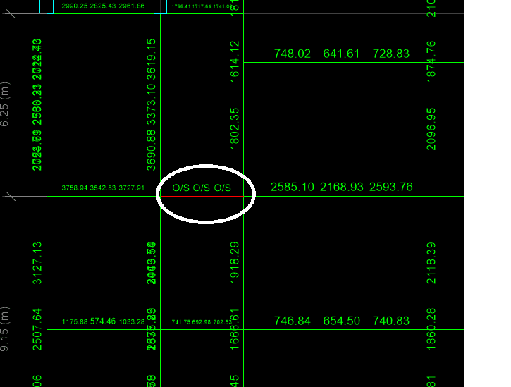
What is the detailing of a beam modelled as pin into a column, though there are beams at its start and end (longitudinally)? Also, is this allowed to pin connect the short beams in SMF to avoid shear failure of that beam? Or are there anymore ways to avoid this failure?

Reference:
Pic_qxe0s6.png
 
Replies continue below

Recommended for you

You could do a bearing ledge and smooth dowels. However, what is the floor sitting on this beam? If it is going to tie everything together, then you may not get the true pin action you're expecting.
 
The building is 6 storied. This beam fails at every level except roof. What if, i allow some moment at ends (partial fixity) and provide the reinforcement for that moment at ends, and detail as required for rigid joint for that reinforcement, so that the Reinforcement remains below that which would cause higher Mpr to fail the beam in Shear.
 
Moment redistribution is what I'm thinking about. Is this allowed, or restricted in New design? Note that the building is in SDC D. SMF required.
 
I'm going to let the guys with much more experience in seismic design chime in for the majority of your question. I personally do not believe in partial fixity, especially in concrete. You're either transferring moment, or you're not.
 
I would be asking why there is a need to avoid a shear failure in that beam? Looking at your drawing, it should not be that bad. What is causing the shear failure?

Moment redistribution cannot be used to provide a pin and would not reduce the possibility of a shear failure that much.
 
To jayrod12 : ok
To rapt:I am not clear about "why there is a need to avoid a shear failure in that beam?", shouldnt i try to make it ok if it theoretically fails when quake occurs. "What is causing the shear failure?", it has high negative reinforcement at supports, as per code there will be high probable moment, due to short span the shear ((Mpr(left)+Mpr(right))/clear span of beam) coming from these Probable moments assuming the beam hinges at support, causes the beam to fail.
 
What are the depth and span of your beam?
Do you need the short beam to function as part of your lateral system or do you just need it to ride along without losing its gravity load carrying capacity?

I think that limiting shear demand by limiting moment capacity is a valid approach if you consider over strength and the proportions of the beam are such that you can plausibly develop two plastic hinges within the beam length. It's not that different from how we design shear in normal SMF beams after all.

You might also.detail the beam as you would a coupling beam connecting shear walls. Diagonal reinforcing that crosses at midspan and effectively puts your pin there.
 
Well, thanks KootK. i want to know about "excluding a member from lateral force resisting system (LFRS)", i just want it to carry the gravity loads in this case, as its failing. what are the code provisions regarding it. can i just design it as in IMRF keeping it in the model, or what do i do? if i dont want it to contribute to the LFRS, how do i do it?
I am not much aware about detailing a coupling beam connecting a shear wall, please enlighten by sharing some information.

 
Assume the beam is 10 feet center to center, and section is 500X600(bXh)

 
NewbieInSE

As usual we do not know enough. Is it an existing building or design for a new building.

if design for a new building, surely there is no problem designing for the shear. The beam on the other side of the column connecting to it is designed for the shear also.

Allowing a pin goes against all design rules unless you fully detail it as a pin. 100% redistribution is not allowed. I certainly would not like it designed so that it has to basically fail to form the pin. I doubt that it would survive as a vertical load carrying member in an earthquake in that situation. And bottom reinforcement has to be detailed for an end span condition.

And if you detail it as a pin (ie no moment capacity), you have to make sure it is tied to the column/beam it is connecting to. Is that feasible and still have it working as a pin.
 
rapt. Thanks for your comment. "I certainly would not like it designed so that it has to basically fail to form the pin." This is a very important thing u have mentioned. Maybe i shouldn't make it pin. The section is not contributing in Shear resistance theoretically, because shear due to sway is higher than 50% of total shear (due to sway+gravity loads) as per ACI318. In that case what do you suggest?
I couldn't catch the meaning of "it is tied to the column/beam it is connecting to.' Do you mean running some bottom and top reinforcement beyond the joint?
 
Given the proportions of your beam, detailing it with diagonal reinforcing like a shear wall header won't work. I'd do as your originally proposed and limit your flexural reinforcing to as little as you can get away with and then capacity design your shear capacity to suit those moments. Provide enough stirrups to handle the entire shear demand without the aid of concrete shear capacity to compensate for the fact that, when cyclic plastic hinges form at the ends of the beam, they'll tend to diminish the concrete contribution.
 
Status
Not open for further replies.

Part and Inventory Search

Sponsor