Good Evening,
I would like to ask a question about pile head moments in a simple bridge abutment model.
I have modeled two simple frame element models on SAP. The models are in longitudional direction and they look like this:
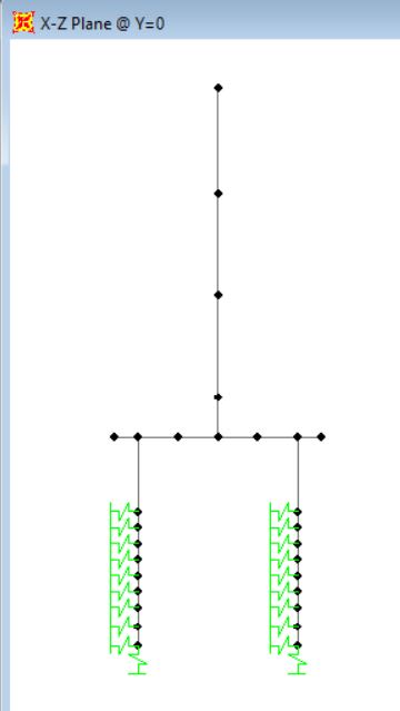
What both models have in common are:
1_ 4.5m design width
2_ Abutment stems are 2.5m x 4.5m
3_ Pile cap is 2.5m thick x 4.5m
4_ piles are 1.2m dia (2 piles per 4.5m design width)
The difference is:
1_Model 1 has 3.6m distance c/c between piles
2_ Model 2 has 5m distance c/c between piles.
The issue is I am getting vastly different Pile head moments for both models. I am trying to figure out why there are so vastly different. I know rotational stiffness (which takes length of frame in to account) will make some difference. But is it that much of a factor?
When I take away the soil springs and put fixed supports at the base of the piles, I get similar pile head moments for both models with only 100-200kNm difference. But when I introduce soil springs in to the model, the pile head moments vary greatly. I have checked the placement and vaules of the soil springs in both models and they are correct. So when there are soil springs, what causes the models to behave much differently and have huge difference in pile head moments?
Note: All below models do not have self weight.
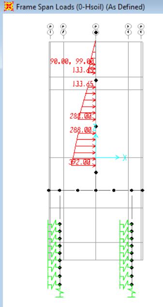
Below shows the two different models have the same soil loads on the stems:
for 3.6m c/c model:
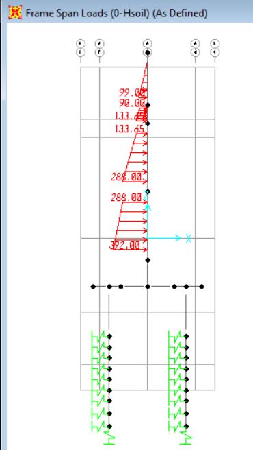
for 5m c/c model:
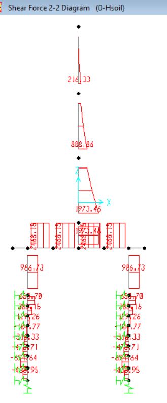
Shear though piles for 3.6m c/c model:
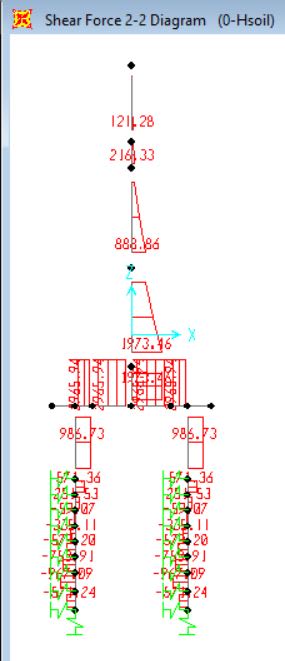
Shear through piles for 5m c/c model: (Note both has same pile shears)
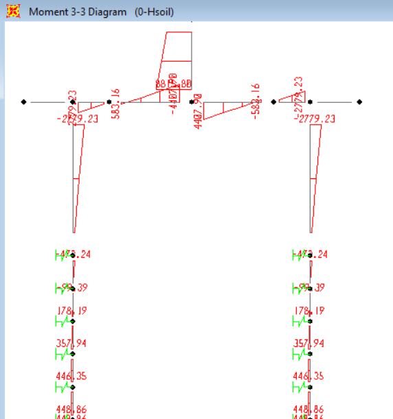
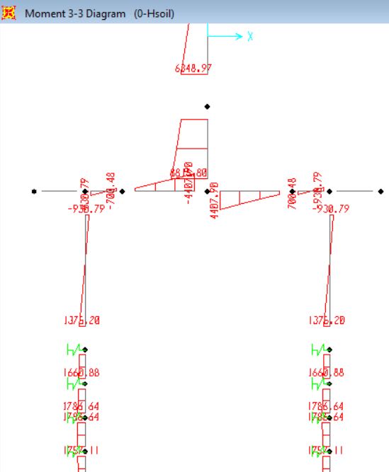
Moments for 3.6m model with springs: 930kNm pile head moment
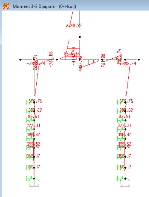
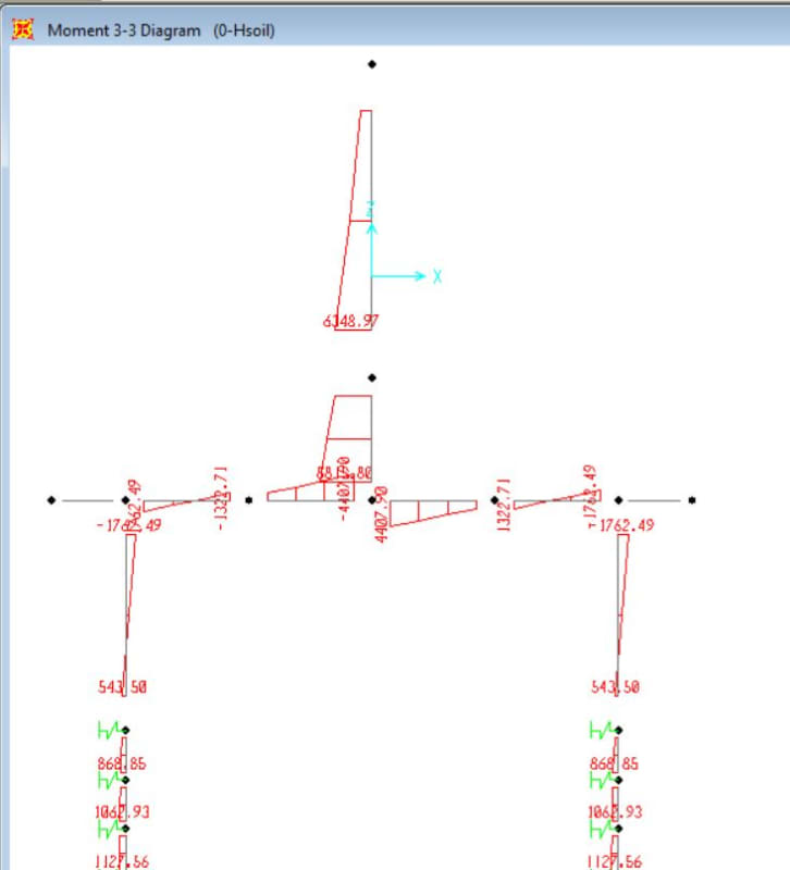
Moments for 5m model with springs: 1762kNm pile head moment

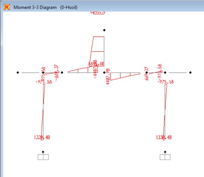
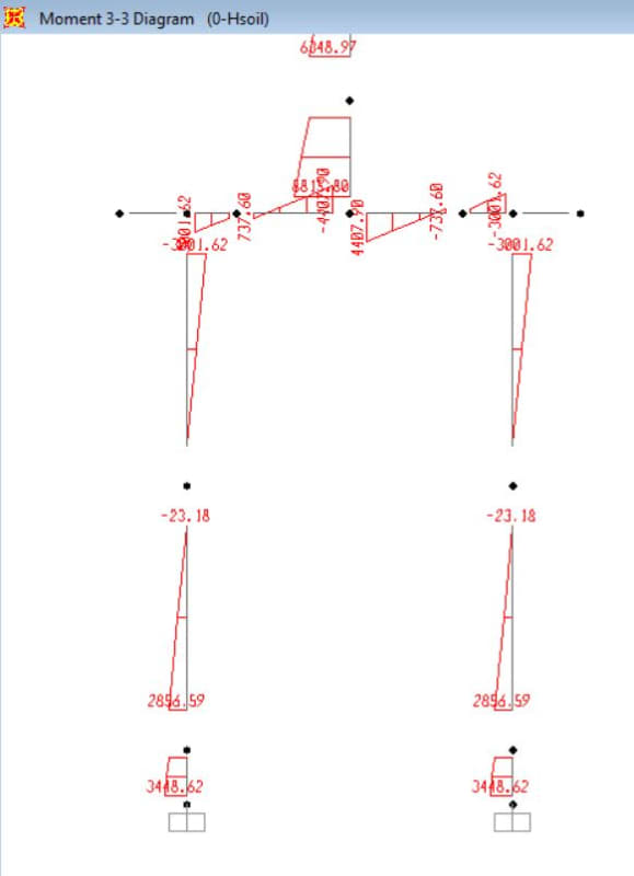
After supports fixed, with no springs, moments for 3.6m model: 3000kNm pile head moment
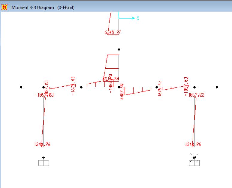
After supports fixed, moments for 5m model: 3100kNm pile head moment
You can see, when supports are fixed, there is very little difference in pile head moment. When spring supports are introduced, the moment varies greatly (1762kNm vs. 930kNm). Why does this happen? Is this actually realistic? Thanks.
I would like to ask a question about pile head moments in a simple bridge abutment model.
I have modeled two simple frame element models on SAP. The models are in longitudional direction and they look like this:
What both models have in common are:
1_ 4.5m design width
2_ Abutment stems are 2.5m x 4.5m
3_ Pile cap is 2.5m thick x 4.5m
4_ piles are 1.2m dia (2 piles per 4.5m design width)
The difference is:
1_Model 1 has 3.6m distance c/c between piles
2_ Model 2 has 5m distance c/c between piles.
The issue is I am getting vastly different Pile head moments for both models. I am trying to figure out why there are so vastly different. I know rotational stiffness (which takes length of frame in to account) will make some difference. But is it that much of a factor?
When I take away the soil springs and put fixed supports at the base of the piles, I get similar pile head moments for both models with only 100-200kNm difference. But when I introduce soil springs in to the model, the pile head moments vary greatly. I have checked the placement and vaules of the soil springs in both models and they are correct. So when there are soil springs, what causes the models to behave much differently and have huge difference in pile head moments?
Note: All below models do not have self weight.
Below shows the two different models have the same soil loads on the stems:
for 3.6m c/c model:
for 5m c/c model:
Shear though piles for 3.6m c/c model:
Shear through piles for 5m c/c model: (Note both has same pile shears)
Moments for 3.6m model with springs: 930kNm pile head moment
Moments for 5m model with springs: 1762kNm pile head moment
After supports fixed, with no springs, moments for 3.6m model: 3000kNm pile head moment
After supports fixed, moments for 5m model: 3100kNm pile head moment
You can see, when supports are fixed, there is very little difference in pile head moment. When spring supports are introduced, the moment varies greatly (1762kNm vs. 930kNm). Why does this happen? Is this actually realistic? Thanks.