Perpendicularity (or Axial Runout) is one of those that seems intuitive at first but actually isn't quite what you think on closer inspection. For this I'll be considering perpendicularity of a face and have my ISO hat on.
As an attribute inspection it's fine, the face is either completely inside the tolerance zone or it isn't. However when measured on the CMM it's given a value and interpreting what this means is perplexing.
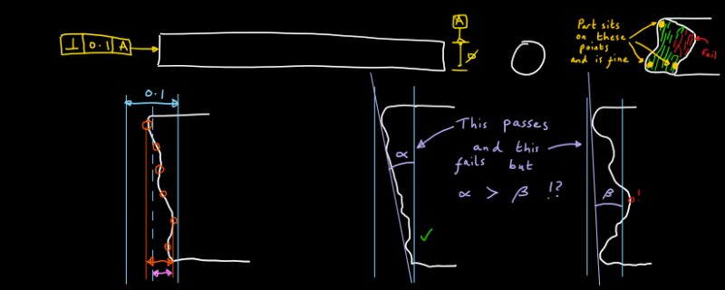
Is it just reporting the difference between the highest and lowest points (with the height direction dictated by Datum A)? In my drawing this is the orange arrow.
Or is it reporting the largest deviation from a nominal point (pink arrow). I presume not as this would require a basic dimension or something to define the nominal.
So that's my first question: what is the CMM value reporting?
My second perplexion is how it doesn't really control what you actually think it does.
My intuition says a face with good perpendicularity should sit on a flat surface such that the axis it is perpendicular to is also perpendicular to the flat surface.
But as you can see from my drawing this isn't so, a face that was dished for example could fail perpendicularity and actually sit better than a part that passed.
I can hear you saying "axial runout will eliminate the dishing issues" but what about a situation with axial lobing for lack of a better phrase. I've attempted a sketch but you'll have to use your imagination.
So my second question is does everyone just accept this quirk or is there another way to define this behaviour?
Thanks
As an attribute inspection it's fine, the face is either completely inside the tolerance zone or it isn't. However when measured on the CMM it's given a value and interpreting what this means is perplexing.
Is it just reporting the difference between the highest and lowest points (with the height direction dictated by Datum A)? In my drawing this is the orange arrow.
Or is it reporting the largest deviation from a nominal point (pink arrow). I presume not as this would require a basic dimension or something to define the nominal.
So that's my first question: what is the CMM value reporting?
My second perplexion is how it doesn't really control what you actually think it does.
My intuition says a face with good perpendicularity should sit on a flat surface such that the axis it is perpendicular to is also perpendicular to the flat surface.
But as you can see from my drawing this isn't so, a face that was dished for example could fail perpendicularity and actually sit better than a part that passed.
I can hear you saying "axial runout will eliminate the dishing issues" but what about a situation with axial lobing for lack of a better phrase. I've attempted a sketch but you'll have to use your imagination.
So my second question is does everyone just accept this quirk or is there another way to define this behaviour?
Thanks