Continue to Site

Eng-Tips is the largest engineering community on the Internet

Intelligent Work Forums for Engineering Professionals

  • Congratulations cowski on being selected by the Eng-Tips community for having the most helpful posts in the forums last week. Way to Go!

Parallel Beams

Status
Not open for further replies.

JonJonSon

Structural
Jan 17, 2020
3
Hello all, I am looking at two parallel beams but have my suspicions on using parallel axis theorem. It seems the beams the "overall" member will be too stiff and therefore not representative.

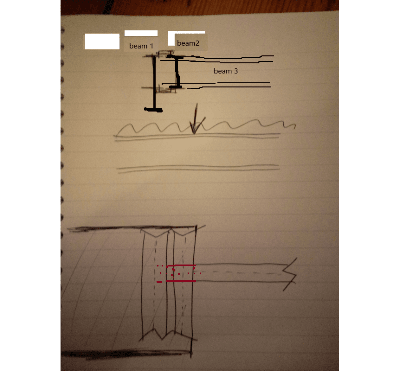
Generally the "beam set" supports a slab and a point load.
Beam 1 supports majority of the slab.
Beam 2 supports a small amount of slab and a point load.
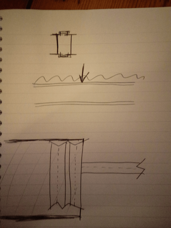
Sketch uploaded.

Could you recommend an approach to analysis?
My thinking is beam 1 standard UDL, Beam 2 UDL + point load.
My issue comes when thinking about LTB and designing connection stiffness.

Many thanks.
JJS

Parallel_Beams_rg2fij.png
 
Replies continue below

Recommended for you

Why you need two beams at such close distance, what is the purpose?
 
I agree - two beams so close seems strange.
The reason is because the span requires a beam that is to deep "architecturally" - so a solution for a smaller beam is required.
Additionally the hope is to use the small space between the beams as a running rail for a shutter.

 
Not really sure what the intent of it is, but you'll also want to keep in mind the shear flow to design the connectors to ensure the composite behaviour.
 
That's really complicated when you consider the deflection compatibility and that the two beams have different loading and slope/deflection curve shapes.

Beam 1 wants to deflect in the middle while Beam 2 wants to deflect closer to the point load. The slab wants them to deflect the exact same the entire length.

Is it possible to drop Beam 2 down a small elevation and only have it support the perpendicular beam and not tie the two together?

Alternatively, design the two beams as essentially one built-up section and check for the torsional effect on the combined section of more slab load on the left side and point load from the beam reaction on the right. If you can create an interior "box" shape, you can handle the torsion a lot better.
 
Can you do this, end beam 1 on beam 3, and run beam 3 all the way to beam 2. {See revised comment below BA's]

[Mis-labeled Graphic Deleted]
 
I don't understand the original sketch, including the numbering of the beams.

BA
 
Can you do this, end beam 2 on beam 3, and run beam 3 all the way to beam 1.

Untitled_xtzgha.png


BA, Thanks for the catch. Now the layout is consistent with OP's description, except the labeled "beam 3".

I believe beam 2 is the floor support beam with beam 3 framing into it. Beam 1 is required for architectural reasons, the proximity of beams 1 & 2 create uncertainty as how to analysis this situation, as torsion is concerned.
 
JonJonson said:
I am looking at two parallel beams but have my suspicions on using parallel axis theorem. It seems the beams the "overall" member will be too stiff and therefore not representative.

1) I don't believe the parallel axis theorem is relevant.
2) "too stiff" for what and "not representative" of what?

The total load can be shared equally by each beam. If the beams are separated by distance 'd' and the torsional moment is Mt, Mt/d must be added to the load on one beam. Beams should be rigidly tied together using WF or channel separators whose flanges are attached to each web full height at a spacing determined by engineering judgment.

BA
 
BA is correct, the parallel axis theorem would apply if the two beams were stacked and properly welded/bolted together to make a deep composite beam. For beams side-by-side it is not applicable, even if the two beams are connected.

For two beams, side-by-side, the moment of inertia (MOI) of the two beams (sharing a load equally) is the sum of the MOIs for the two beams. Same for the section modulus (S).

We don't have a clue what depth the beams are, but perhaps the OP can see if one beam of the same depth (with a wider flange, therefore greater "I" and "S") can be used instead of side-by-side beams.

Perhaps another option may be to add cover plates to one beam... it won't take much to double "I" and "S". Make sure the web is not too "thin".

CoverPlate-600_gg59i8.png


Another possible approach; if beam depth is suitable, use an HP section as a (non-compact) beam... extra wide flanges, giving high values of "I" and "S" for their depth. Should be no problem with web thickness, for HP web thickness = flange thickness.

HP-600_pkjiqc.png


[idea]
 
Agree with BAretired....parallel axis theorem is irrelevant. Side by side beams the properties are directly additive, but you have to account for torsion.
 
If you're going to do the twin thing, I recommend detailing it in such a way that you've got:

1) Positive vertical shear transfer so that the beams can be plausibly claimed to share load well.

2) Positive longitudinal shear transfer so that the beams can be plausibly claimed to form a closed section for torsion.

Space permitting, my preferred solution here would be SlideRule's cover plate suggestion:

3) It's simple.

4) It's easy to fabricate.

5) It could be made to provide the same flexural capacity as the twin beams.

6) Most importantly, it eliminates most of the complications that arise from having to deal with significant torsion.

As a matter of interest, a very similar thing is done (twin beams) for supporting new openings in wide masonry wall systems.

c01_fkuubf.jpg
 
JonJonSon,

I am looking at two parallel beams but have my suspicions on using parallel axis theorem. It seems the beams the "overall" member will be too stiff and therefore not representative.

I wonder why you thought of "parallel axis theorem" at the beginning, then turned to "suspicious" on using it? Also, can you elaborate more on "the overall member will be too stiff therefore not representative", too stiff for what, thus makes it not representative?
In my opinion, parallel axis theorem is irrelevant if torsion on the built-up section is the only concern.

The built-up beam in your sketch shall be able to handle torsion, after stiffened by adding diaphragm elements in the space between the two beams at a regular interval along the length, as suggest by the others. However, it is quite complicate in design, and construction as well.

What exactly the "architectural beam" does? Does it must be the same depth/size as your floor support beam? I am thinking the possibility to make it a real architectural beam - that is not to take loads from slab above by separation, or can you use rectangular HSS shape to achieve both needs - structural and architectural?

Finally, have another look on the suggested beam arrangement at my sketch. If acceptable, both design and construction should be quite simple (all simple shear connections).
 
Thank you for the great info everyone - I haven't dealt with twin beams before so on a learning curve.
 
Status
Not open for further replies.

Part and Inventory Search

Sponsor