Tek-Tips is the largest IT community on the Internet today!

Members share and learn making Tek-Tips Forums the best source of peer-reviewed technical information on the Internet!

  • Congratulations LittleInch on being selected by the Eng-Tips community for having the most helpful posts in the forums last week. Way to Go!

Outlines issue

  • Thread starter Thread starter rogigor
  • Start date Start date
R

rogigor

Guest
Hi,

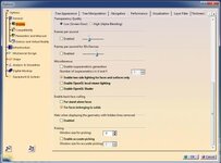
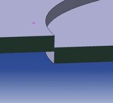
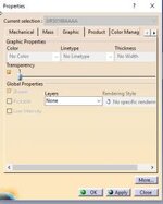
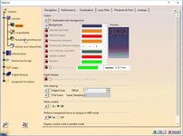
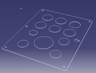
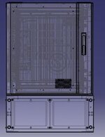
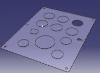
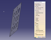
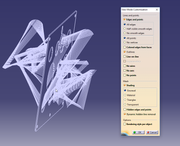
Whenever I customize my view mode to see outlines, I see way to many lines that are not visible in any other view mode. Is there any way to hide them?
The same view on my friend's computer opens correctly - without those lines (we have the same catia version).

 
This is a graphic glitch. Your GPU may be too weak and it is having problems with interpreting some data. BTW, see those faces inside the holes on the right image? They definitely shouldn't be there. Try remaking the solid (Extract a full boundary of the solid and make a new pad of it - see if the surfaces are there. Or try playing around with some CATIA display options(see below). I have a really good CAD station at work but I've seen some surfaces stretching out like that. I think this occurs during importing from another format like STP or IGS. Can you upload that model here anyway? I'll take a closer look.


View attachment 2275
 

Attachments

  • Przechwytywanie.jpg
    Przechwytywanie.jpg
    17.5 KB · Views: 3
I don't think it's a glitch. A couple of friends have the same laptop model with integrated graphics card and they don't see those lines.
Attached is the .stp file.View attachment 2276
 

Attachments

Yea well different GPU processors interprete some things differently (ATI and NVIDIA). I can't really say what does your PC do when you're opening that model. Anyway, there is a very tiny intersection or a contact between those bodies. This is what probably bothers the STP interpreter. Try adding a 0.01mm to one of the faces if that's not a problem. When you saved the STP from another cad software (which is what I assume you did?) were the bodies supposed to be connected or disconnected?

View attachment 2280
 

Attachments

  • Przechwytywanie.jpg
    Przechwytywanie.jpg
    4.9 KB · Views: 1
I updated the graphics drivers and it did not help.
To be honest I do not know where to add 0.01mm to one of the faces. Could you give me some hint?

Anyway I think I found a solution. If I set the whole object's transparency to 1 and check "Perform transparent faces as opaque in HRD mode" those lines are gone. However it does affect other view modes and I work with them interchangeably. Look at the screens below. Any ideas?

View attachment 2281View attachment 2282View attachment 2283View attachment 2284View attachment 2285
 

Attachments

  • settings.jpg
    settings.jpg
    10 KB · Views: 1
  • settings 2.jpg
    settings 2.jpg
    17.9 KB · Views: 1
  • OK.jpg
    OK.jpg
    9.2 KB · Views: 1
  • shading.jpg
    shading.jpg
    9.5 KB · Views: 3
  • shading2.jpg
    shading2.jpg
    10.7 KB · Views: 3
Not sure if this will help, but the latest set of attached pictures look like perspective views. Try this: Click the View menu on top of the screen, then click Raster Style and Parallel.
 
Unfortunately it didn't.
 

Part and Inventory Search

Sponsor

Back
Top