Hello All,
This is going to be a double post because I accidentally posted this in the structural engineering forum before I found this bridge specific forum. If someone knows how I can delete the other so there’s no duplicate please let me know.
I'm new to posting to the forums but I have found many helpful recommendations in the past via these forums! So thanks to all in advance for your input!
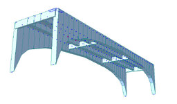
I am working on a load evaluation of a somewhat unique bridge. A picture is attached as I am not quite sure what this bridge type would be called.
It is almost like an open spandrel arch bridge, except the entire arch is solid, as opposed to consisting of ribs. The deck has two stringers and two floorbeams. The old drawings are attached as well for reference.
I am curious if someone could provide input on how these exterior arches would be checked for capacity? I don't think looking at the exterior arch as a variable depth beam between abutments for flexure would be accurate, but I am stuck as to the best way to analyze the arch?
Any input and/or resources would be greatly appreciated!

In response to comments I received in the other forum, more info below:
My understanding for the load path is that the interior stringers span between the floor beams and the floor beams bring the load to the exterior arch. Based on the size and reinforcing in the stringers, I don’t think they would have ever been designed to span the full distance between abutments.
1” bar is twisted square rebar. Given the age of the structure and no cores to confirm concrete strength means CSA S6 (Canadian Highway Bridge Design Code) requires I assume a 20MPa compressive strength and I use 230 MPa for the steel reinforcing.
I am analyzing the bridge for specific fire trucks to determine if they may pass in case of emergency, which allows me to use reduced live load factors
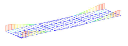
My first simplified approach was as you said, analyzing the exterior beam ignoring the structural capacity of the arch (but including the weight) but under those conditions the beam wouldn’t even support the dead load of the structure. I then modelled a 2D structure in MIDAS (FEA software) using frame elements with variable depth for the exterior beam to try and capture the pull of moments towards the deeper part of the beam but that still didn’t work. Fixing the end of the frame elements drastically reduced loads at mid span but resulted in very significant negative moments at the ends which exceeded the negative moment capacity even when considering the 15’ depth of the beam. Snapshots of model and results under own weight for reference attached. I have a hard time believing these exterior girders act as a simplified beam in flexure like this.
My next thought was modelling the arches as plate elements. I can model the plates and assign an 18” thickness to the properties of the plate members; however I don’t have experience in how to convert the results for these plate elements from their force/m outputs of nodal forces into a form which I can compare member capacities via the code. If anybody has suggestions or literature or tutorials for this, I’d love to learn more about it.
However if’s there is a more simplified way of looking at this arch than plates id like to explore that avenue as well.
This is going to be a double post because I accidentally posted this in the structural engineering forum before I found this bridge specific forum. If someone knows how I can delete the other so there’s no duplicate please let me know.
I'm new to posting to the forums but I have found many helpful recommendations in the past via these forums! So thanks to all in advance for your input!
I am working on a load evaluation of a somewhat unique bridge. A picture is attached as I am not quite sure what this bridge type would be called.
It is almost like an open spandrel arch bridge, except the entire arch is solid, as opposed to consisting of ribs. The deck has two stringers and two floorbeams. The old drawings are attached as well for reference.
I am curious if someone could provide input on how these exterior arches would be checked for capacity? I don't think looking at the exterior arch as a variable depth beam between abutments for flexure would be accurate, but I am stuck as to the best way to analyze the arch?
Any input and/or resources would be greatly appreciated!
In response to comments I received in the other forum, more info below:
My understanding for the load path is that the interior stringers span between the floor beams and the floor beams bring the load to the exterior arch. Based on the size and reinforcing in the stringers, I don’t think they would have ever been designed to span the full distance between abutments.
1” bar is twisted square rebar. Given the age of the structure and no cores to confirm concrete strength means CSA S6 (Canadian Highway Bridge Design Code) requires I assume a 20MPa compressive strength and I use 230 MPa for the steel reinforcing.
I am analyzing the bridge for specific fire trucks to determine if they may pass in case of emergency, which allows me to use reduced live load factors
My first simplified approach was as you said, analyzing the exterior beam ignoring the structural capacity of the arch (but including the weight) but under those conditions the beam wouldn’t even support the dead load of the structure. I then modelled a 2D structure in MIDAS (FEA software) using frame elements with variable depth for the exterior beam to try and capture the pull of moments towards the deeper part of the beam but that still didn’t work. Fixing the end of the frame elements drastically reduced loads at mid span but resulted in very significant negative moments at the ends which exceeded the negative moment capacity even when considering the 15’ depth of the beam. Snapshots of model and results under own weight for reference attached. I have a hard time believing these exterior girders act as a simplified beam in flexure like this.
My next thought was modelling the arches as plate elements. I can model the plates and assign an 18” thickness to the properties of the plate members; however I don’t have experience in how to convert the results for these plate elements from their force/m outputs of nodal forces into a form which I can compare member capacities via the code. If anybody has suggestions or literature or tutorials for this, I’d love to learn more about it.
However if’s there is a more simplified way of looking at this arch than plates id like to explore that avenue as well.