Continue to Site

Eng-Tips is the largest engineering community on the Internet

Intelligent Work Forums for Engineering Professionals

  • Congratulations 3DDave on being selected by the Eng-Tips community for having the most helpful posts in the forums last week. Way to Go!

Old Through Plate Girder Bridge

tmalik3156

Structural
Jun 21, 2021
109
Good day all.
This old railway bridge will be converted to a pedestrian bridge. There is no drawings available.
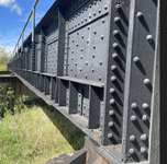
It's a built up riveted through plate girder bridge consisting of angles and plates. To do a load rating, we need no know cross sections of the girders. We will take as much field measurements as possible. But just wondering, if it is possible to guess the cross section from the photo below.
Screenshot 2025-06-09 180045.png
If we ignore the stiffeners, would the cross section look like the one below?
Does any one have design drawings for such girders?
Thank you
 

Attachments

  • X-sec.png
    X-sec.png
    2.8 KB · Views: 15
Last edited:
Replies continue below

Recommended for you

A doubled web would be unusual, but otherwise your cross section is likely true.

If I presume a common 7/8" rivet, it looks like maybe a 72" tall web, L8x8x3/4" flange angles, 18"x3/4" cover plates.

Then stiffened up the wazoo! Although many of those would be neglected for basic load rating calculations, aside from increasing the dead load.

I have lots of design drawings for similar bridges-- what do you need to know?
 
@Lomarandil Thank you for your prompt reply. We thought it would be a double (back-to-back) web because of those rivets on the web. We don't know what else are those rivets for.
If you have pre-1960 drawings of riveted through plate bridges, it would be great if you could share sheets that have the structural steel cross sections.
 
Last edited:
Do some thickness checks on the plate.

Also that top angle doesn't look too be continuous or the same depth. Only one row of rivets in the middle compared to 2 closer to the camera.
 
You'll have to measure everything to model the cross sections. However, assuming this was a bridge carrying standard freight rail loads, unless there's substantial section loss in key locations, the load carrying capacity for pedestrian loads or maintenance vehicles is unlikely to be a limiting factor.
Also that top angle doesn't look too be continuous or the same depth.
It looks to me that the angle is continuous through the span, but it has multiple cover plates, some of which only extend over portions of the span, similar to the ones on the bottom. There's extra rivets at the ends of each of the cover plates. In the middle, there would not be many fasteners needed to maintain continuity.
 
I agree with Rod. If the bridge carried trains it can certainly carry pedestrians or an H-10 truck. You can't get away from field measurements. Side plates add a lot of capacity.
 
@Lomarandil Thank you for your prompt reply. We thought it would be a double (back-to-back) web because of those rivets on the web. We don't know what else are those rivets for.
If you have pre-1960 drawings of riveted through plate bridges, it would be great if you could share sheets that have the structural steel cross sections.
Screenshot 2025-06-10 084108.png
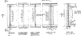
Here's one, 1952 riveted plate girder. Hope the resolution works.
 
@LittleInch , Yes we will measure thickness with ultrasonic thickness gauges.
@BridgeSmith , Yes, in this simply supported girders, plates were added to the flanges to resist higher moments at mid-span.
@bridgebuster , That's what we expect.
@Lomarandil , I appreciate your sharing the drawings. We expect our bridge girder to have similar x-section, but with more plates added to the web.
 
Also just noticed like lomarandils drawing, the bottom web (and also the top web? )has more plates in the middle of the span - looks like max 4 plates extra and then gradually tailing off.

You can see the effective arch on the second span.

Screenshot 2025-06-11 112855.png
 

Part and Inventory Search

Sponsor