George_4800
Student
- Jan 29, 2022
- 3
Hello there,
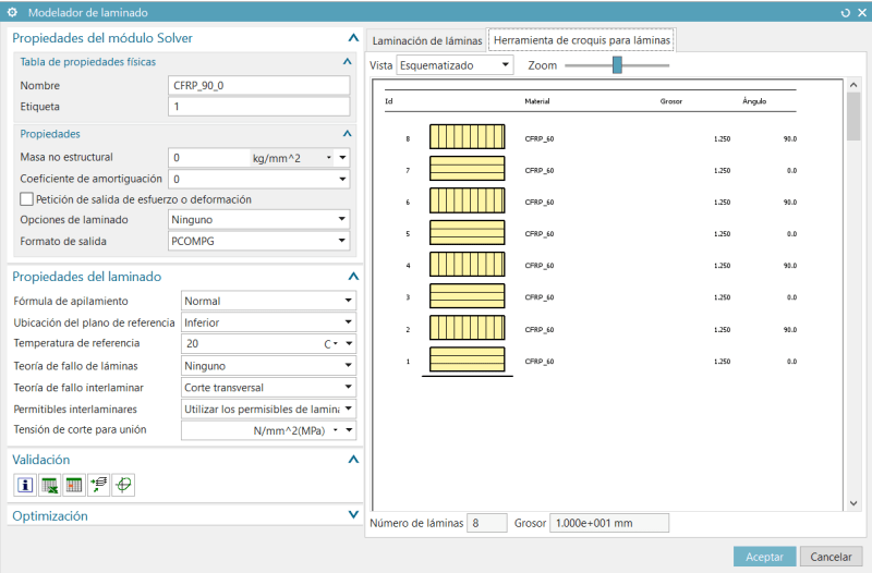
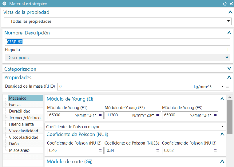
I'm currently working on a FEA project that requires to use CFRP (60% Fibre Volume) to make an Hydrogen reservoir. I've modelled the tank with it's given dimensions and meshed it with shell elements. To those shells I've applied the laminate material option (I've previosly created the orthotropic material I'm working with)and applied the plys in the corresponding order.
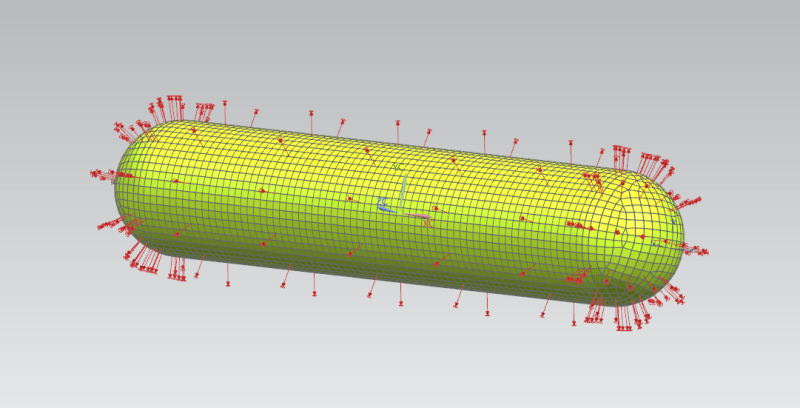
As boundary conditions I've placed two pin supports on both ends of the tank, and loaded it with internal pressure.
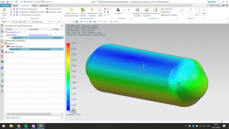
The problem is that I don't get results with some sense and don't know what exactly could be the reason:
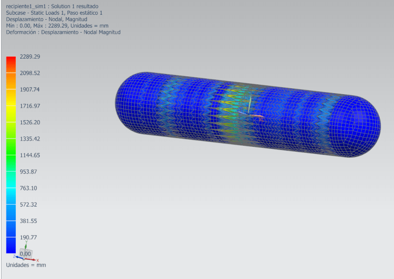
Just to make sure if there was some sort of proble with the mesh I only changed the material to common steel and the results were just as expected:
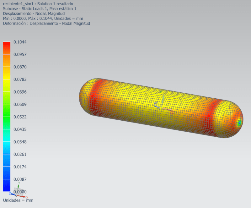
Is there something I could've not taken into account? I think it is some kind of set-up related problem, but to be honest I don't really know what else to do.
I'd appreciate any kind of help / tips.
Thank you in advance,
George
I'm currently working on a FEA project that requires to use CFRP (60% Fibre Volume) to make an Hydrogen reservoir. I've modelled the tank with it's given dimensions and meshed it with shell elements. To those shells I've applied the laminate material option (I've previosly created the orthotropic material I'm working with)and applied the plys in the corresponding order.
As boundary conditions I've placed two pin supports on both ends of the tank, and loaded it with internal pressure.
The problem is that I don't get results with some sense and don't know what exactly could be the reason:
Just to make sure if there was some sort of proble with the mesh I only changed the material to common steel and the results were just as expected:
Is there something I could've not taken into account? I think it is some kind of set-up related problem, but to be honest I don't really know what else to do.
I'd appreciate any kind of help / tips.
Thank you in advance,
George
")