Not a "pressure vessel" but I had to re-design the steam piping into a modest (55 Meg) turbine (built and designed by a competing company) that had been destroyed when the steam piping loading grossly exceeded the turbine nozzle loads. Turbine casing got "pushed sideways" into the turbine blades, blades broke, turbine was destroyed.
The OEM manual was very clear about maximum nozzle loads - which (in my humble opinion) were much too low to be reasonable, but it didn't matter. "Book said these were maximum loads (on the order of +/-150 to 200 lb force total in all directions) on each nozzle under hot and cold conditions." Therefore, my pipe stress team met the conditions, then we verified them by sitting on the turbine and moving each pipe by hand until it kissed the flange with zero force cold. took a few minor adjustments to the pipe hangers, but cold and hot force limits were met.
What were the original design pipe actual loads? We may never know.
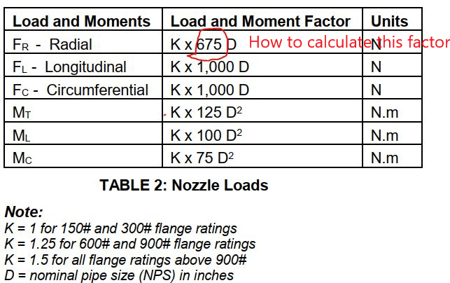
In tis table? Only corporate memory and lessons learned can be invoked. Most likely, NO real stress/strain/3D modeling was ever done to verify these arbitrary guidelines are realistic. They may be too high, and so the allowed nozzle loads are only marginally safe. They may be way too low, and so the needed pipe designs are much "too conservative" and could be relaxed in the real world. A FEA model of the actual PV under design for you "might" work if any single calculated pipe load is too high.