Continue to Site

Eng-Tips is the largest engineering community on the Internet

Intelligent Work Forums for Engineering Professionals

  • Congratulations cowski on being selected by the Eng-Tips community for having the most helpful posts in the forums last week. Way to Go!

Moment Resistance of a Weld 3

Status
Not open for further replies.

Jalbno

Structural
Nov 11, 2020
6
Good day to all,

I have this weld that I am trying to analyze. I understand that it may be somewhat ugly and inefficient, but I am in a position in which I still need to calculate this.

The only reason I am considering this spec is because the load on the end of this beam is very very small.

image_for_forum_woch8x.png


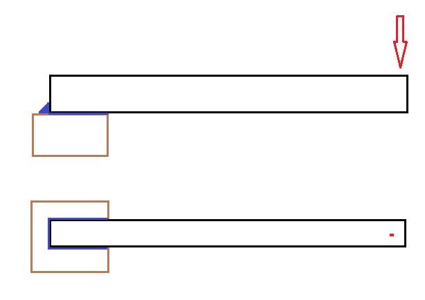
The loaded cantilevered member is a rectangular HSS, welded to the top of this other steel member. I'm worried about the moment resistance of this weld, would I calculate it it using the section modulus of the weld multiplied by the strength of the weld material about the axis of rotation?

Thanks for you time.

NJ
 
Replies continue below

Recommended for you

I've always resolved these situations the way that you are proposing, by finding the section modulus of the weld and comparing it to the factored resistance of the weld in shear & tension. Don't neglect to check failures of both the base metal and weld material, and in both tension (against the horizontal surface) and shear (against the HSS).

Grab a copy of Blodgett's Design of Welded Structures. A snippet of the applicable page is below. The section modulus shown is intended to be used to determine the weld demand in units of force per unit length, but by adding a term related to the weld leg or throat length, you can determine the demand in terms of stress if so desired.
Screenshot_2020-11-11_085737_rzii5b.png
 
I don't disagree with the approach discussed above but will propose and alternate.

C01_lcfcb5.jpg
 
Unless there is a cap plate on the HSS, the welds on the side will provide a much better load path through the HSS than the weld on the end for the force couple being developed. So, even if sized per KootK, I wouldn't forgo the flare bevel welds.
 
Good point, I was assuming a cap plate. Among other things, a cap plate would allow for at least one weld to not be a flare bevel weld (I don't love the QC on those).

Of course, if you're going to get into considering flexibility explicitly, then the flexibility of the cap plate enters in. And that would skew weld effectiveness to the perimeter of the cap plate rather than the middle. And, if the HSS itself flexes at all, then you've got prying effects etc.
 
Use Blodgett's solution. It is proven. I'll try the two lines approach before jump into U shape, especially for small load.
 
You can use the section modulus method but I would just check kootks force couple method. If the back length of weld is good for uplift then it’s good.
 
Tomfh,

There are two possibilities of the location of the applied load , one is at the edge (rigid method), another one is at the center of the bearing area (elastic method). The former will produce highest demand on the end weld, by ignoring the contribution of the weld on sides, it is simple and conservative, but it can cause the plate to lose bearing due to bending curvature. If side welds are added to close the gap, then isn't that going back to the solution of the elastic method?
 
Hello everyone,

Thank you all very much for your responses. Very well explained and detailed, you have helped me greatly!
 
Be careful with those flare-bevel welds. You get just a fraction of the wall thickness as your effective width (5/8 t if I remember correctly).
 
Status
Not open for further replies.

Part and Inventory Search

Sponsor