Dear sushi75,
A picture is better than 1000 words, good!.
You can solve this problem on
FEMAP with NX NASTRAN in say three ways, arriving to similar stress & displacements results. This is true because the cylinder is thick walled and LONG, then the "boundary" effect should be neglected:
1.- 2-D Solid Axisymmetric Analysis:
Axisymmetry occurs when a geometric part is a body of revolution and the loads and constraints acting on the part are only radial and axial, that is, they are cylindrical, with no tangential component. Axisymmetric modeling is useful for body of revolution parts such as pressure vessels. The model is built on an axisymmetric plane X-Z, and rotates around the rotational Z-axis.
Axisymmetric analysis requires you to properly align the center of rotation and the radial axis of the axisymmetric model to the absolute coordinate system. For example, in the NX Nastran environment the center of rotation is the absolute Z-axis, and the axisymmetric plane is absolute XZ. The model must lie in the +X half of the XZ plane (X is the radial direction, and Z is the axial direction).
In NX NASTRAN the axisymmetric elements
CQUADX4 define a solid ring by sweeping a surface defined on a plane through a circular arc.
You can request that NX Nastran output the following stresses, which it evaluates at the three vertex grid points and the element’s centroid:
• σr – stress in rm direction of material coordinate system.
• σθ – stress in azimuthal direction.
• σz – stress in zm direction of material coordinate system.
• τrz – shear stress in material coordinate system.
• Maximum principal stress.
• Maximum shear stress.
• von Mises equivalent or octahedral shear stress.
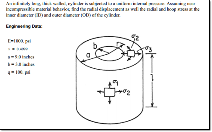
Here you are the 2-D mesh + loads & BCs, together with vonMises nodal stress results:
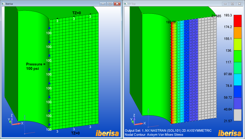
Next here you are the resulting displacements + axial nodal stress:
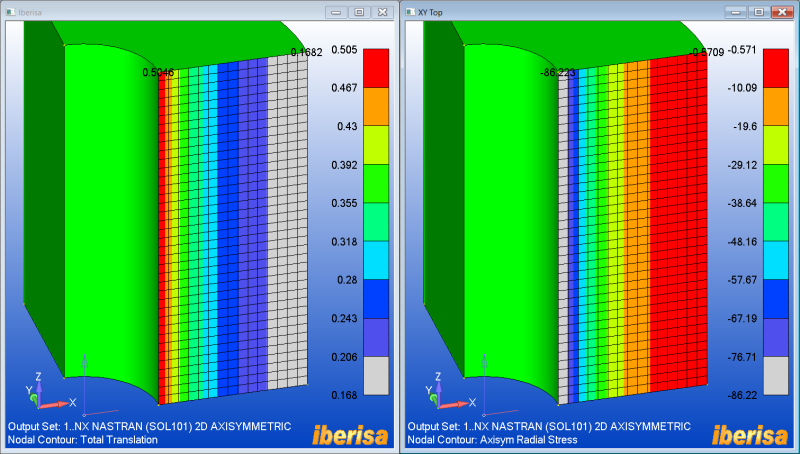
And finally the Axial nodal stress + the maximum nodal principal Stresses:
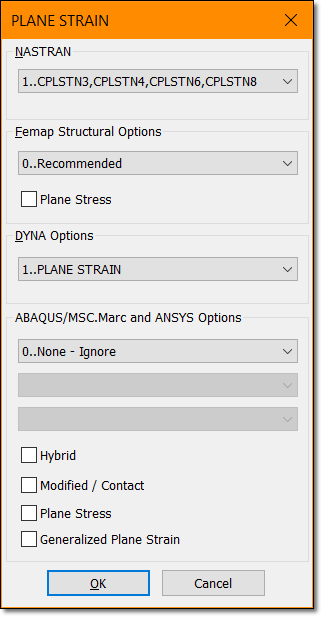
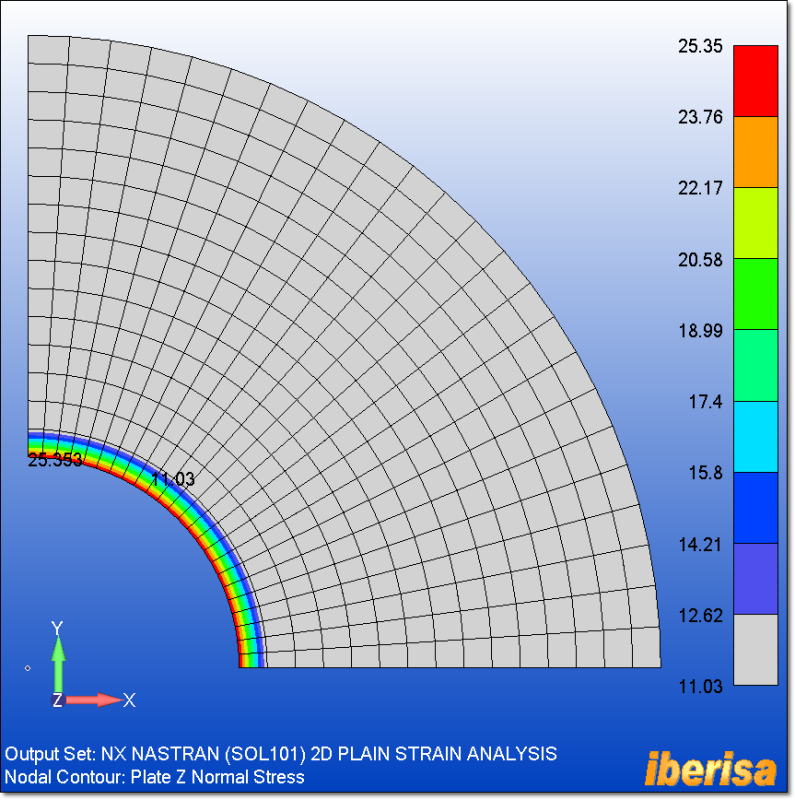
2.- 2-D SOLID PLAIN STRAIN ANALYSIS
Plane strain elements are two-dimensional elements with membrane only stiffness and in-plane loading. The plane strain element idealization has zero strain in the thickness direction. These elements represent structures that are very thick relative to their lateral dimensions. This is the case of the THICK walled cylinder.
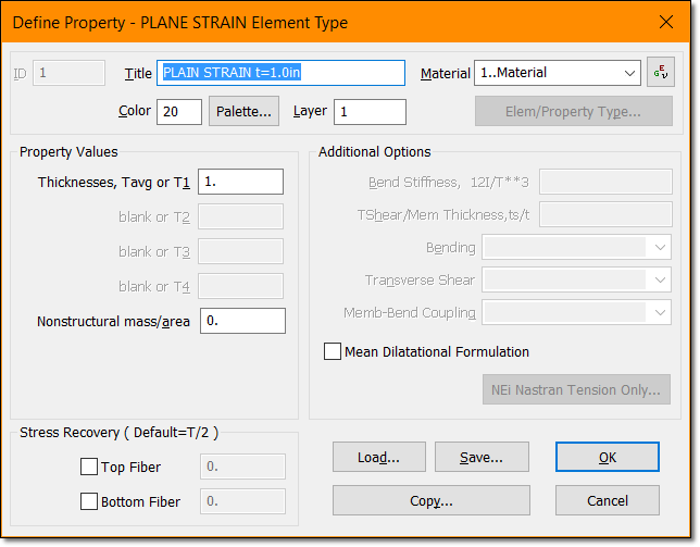
The element used here is the CPLSTN4 4-nodes 2-D solid plain strain element. Please remember to activate the plain strain formulation when selecting in FEMAP the plane strain property: simply use a unitary value for the element thickness:
◦ They must be defined in the X-Y plane of the basic coordinate system.
◦ All loads must be in-plane. The PLOADE1 entry can be used to define edge loads.
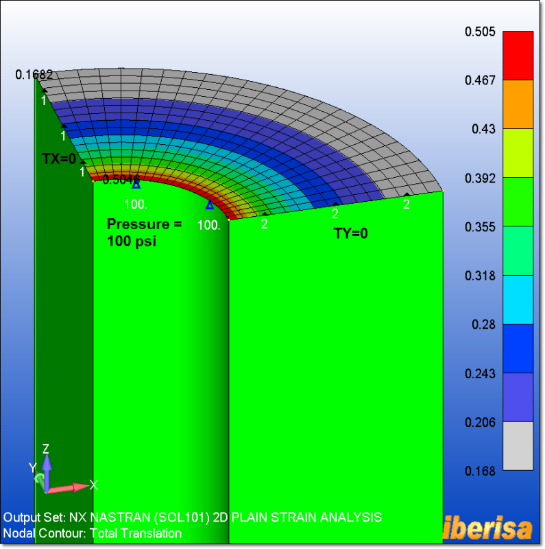
The following picture shows the loads & BCs imposed to the 2-D plain strain model, together with the displacement resaults: you can study any unitary cross section along the cylynder, bacause the cylinder is INFINITELY LONG the result is basically the same, OK?. Then your 2-D meshing approach is capturing perfectly your 3-D Solid problem.
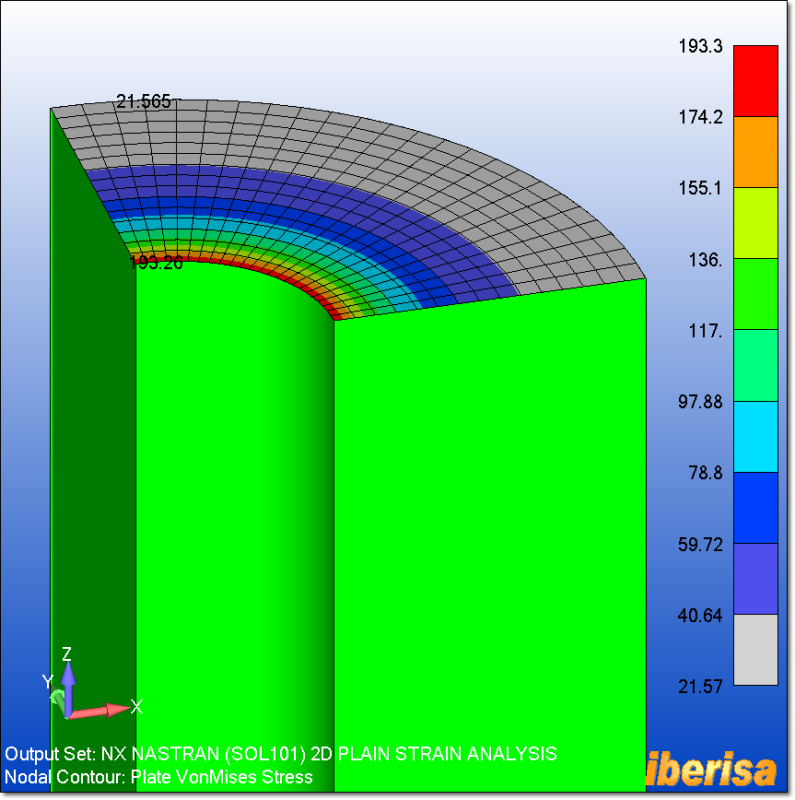
Here you are the vonMises nodal stress of the model, exactly the same value as the axisymmetric analysis.
The Plane Strain z-normal nodal stress is exactly the same as the Axisymmetric Axial Stress:
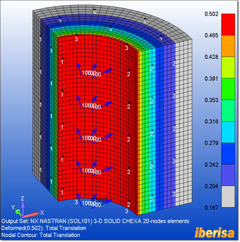
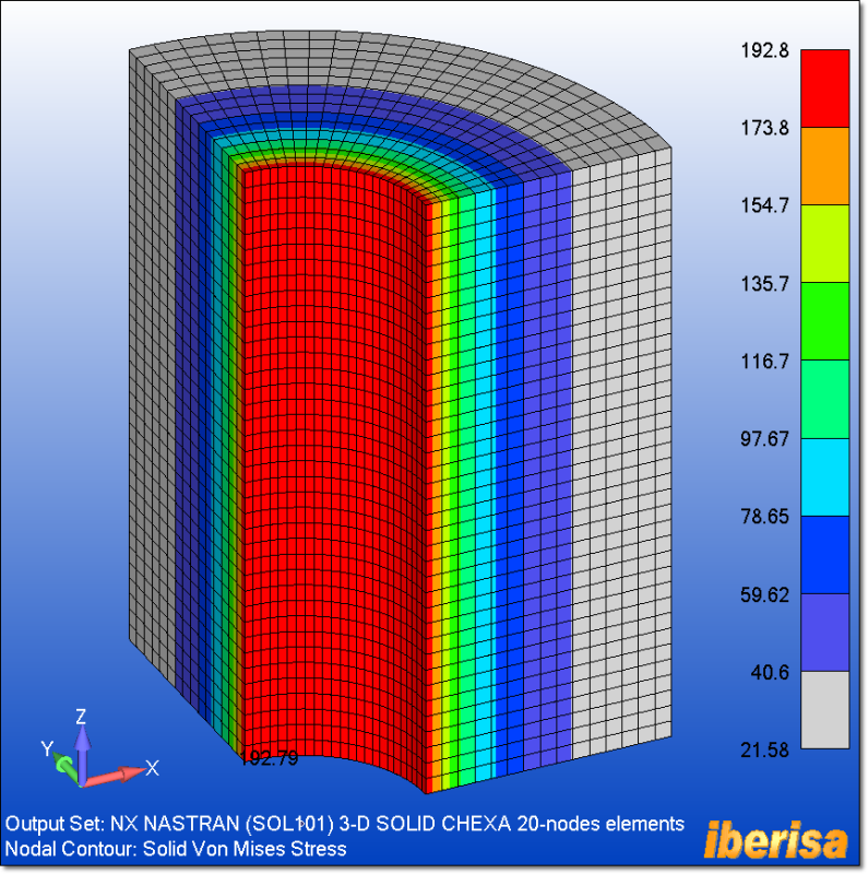
3.- 3-D SOLID CHEXA ELEMENTS
And finally the problem is solved using 3-D solid CHEXA 20-nodes elements, taking in consideration 1/4 of model because we have symmetry of both loads & geometry, in spite of others say the contrary!. Taking advantage of Symmetry BCs is critical, allows you to stabilize the model and arrive to a fast & reliable solution.
The following plot shows the nodal vonMISES stress, with results at the level of the previous analysis. To increase accuracy simply you need to get rid of boundary effect prescribed at both ends: expand the model in the longitudinal direction and the influence of the BCs prescribed at both ends will be negligible.
Best regards,
Blas.
~~~~~~~~~~~~~~~~~~~~~~
Blas Molero Hidalgo
Ingeniero Industrial
Director
IBERISA
48004 BILBAO (SPAIN)
WEB:
Blog de FEMAP & NX Nastran:
") ) is that any strain is resulting from a stress in the same direction.
) is that any strain is resulting from a stress in the same direction.