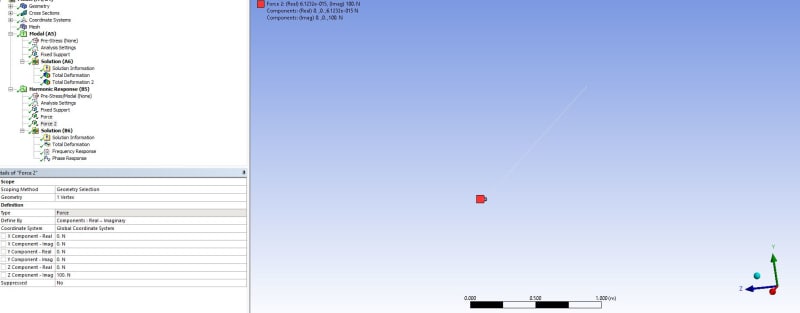
I am working on a rotating shaft with an unbalanced disk. The center of unbalanced disk is located on the mid-span of the shaft with offset=r_shaft. I used SOLID186 to model the shaft. I defined one mass point (MASS21) on the center of the shaft in APDL to model the disk. I know that the unbalance force components (f_x and f_y) cannot applied on a single node as we usually do in the case of beam element. I would like to know how can I properly model the unbalance force on the shaft in transient analysis? My desired output is the elliptic orbit of mid-span point of the shaft.
Eng-Tips is the largest forum for Engineering Professionals on the Internet.
Members share and learn making Eng-Tips Forums the best source of engineering information on the Internet!
-
Congratulations dmapguru on being selected by the Eng-Tips community for having the most helpful posts in the forums last week. Way to Go!
Modeling Unbalance force in solid rotating shaft
- Thread starter iboby
- Start date

