Continue to Site

Eng-Tips is the largest engineering community on the Internet

Intelligent Work Forums for Engineering Professionals

  • Congratulations waross on being selected by the Eng-Tips community for having the most helpful posts in the forums last week. Way to Go!

Modeling Supports for a "U" Shaped Concrete Frame

Status
Not open for further replies.

WarrenG701

Structural
Jul 31, 2019
7
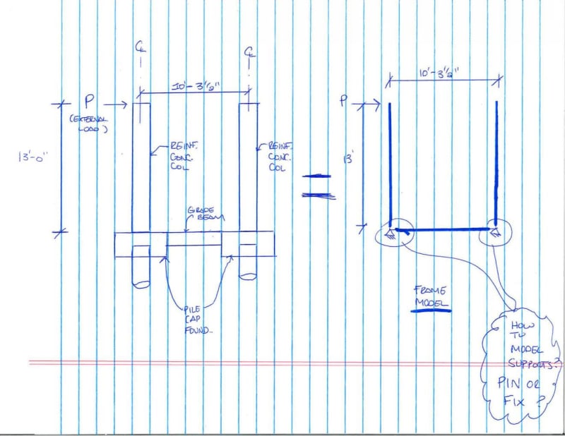
I am currently working on a simple frame that consists of 2 reinforced concrete square columns and a reinforced concrete grade beam at the base of the columns that spans between the support of the columns. The columns are each supported by pile caps and pile foundations at the base and as mentioned above the grade beam spans between the pile caps. There is an external load (P) being applied at the top of the column which creates a moment that is being transferred to the pile caps and into the grade beam. I have attached a sketch of the frame for ease of illustration.

What I am unsure of is how to model the supports of this frame in my structural analysis software. The external load applied at the top of the columns is creating a moment at my pile cap that I want to transfer to the grade beam. I want to design the pile cap to take no moment and have the grade beam do all the work and take all the moment being created from the external load being applied at the top of the column.

My first instinct is to model the frame as a "U" shaped frame with the supports at the bottom being pinned so that the moment is released and my pile cap does not see any moment. Is this the correct approach for modeling such kind of frame? Or do the supports need to be modeled at fixed supports in order to get the transfer of the moment to the grade beam?


Frame_Model_wr9jgr.jpg
 
Replies continue below

Recommended for you

The actual moment in the grade beam and the reactions to the piles will depend primarily on the relative stiffness of the piles, both axially and in bending compared to the bending stiffness of the grade beam. With the piles being embedded in soil, the stiffness could be difficult to estimate with good accuracy, since the depth to fixity and axial displacement of the pile under load vary significantly with variations in the soil properties

For design of the grade beam, the simple and conservative route would be to assume pinned connections to the piles. Conversely, the simple and conservative route for bending in the piles would be to consider the pile connection fixed and the grade beam connections to the pile caps pinned. If everything works with those assumptions, life is good. If not, you'll have to 'sharpen your pencil' and make estimates of the upper and lower bound restraint conditions for the piles, to get less conservative moments in your frame.
 
Hello HotRod10

First and foremost thank you very much for reply.

I understand what you are explaining in terms of the assumptions for the supports when it comes to the design of each individual component.

However, I am still unclear in terms of modeling the supports as an entire system. Does that mean that it should be a pinned base supports or a fixed based support ?


I have read online that a pinned support system will make the piles see no moment but the pile caps will. This moment must be able to transfer from my column to my grade beam and it will also put additional upward/downward load on my piles.
 
However, I am still unclear in terms of modeling the supports as an entire system. Does that mean that it should be a pinned base supports or a fixed based support ?

neither. based on your sketch, you need to come up with a lateral and rotational stiffness estimate for the pile and input that as your support parameter. I'm not sure what software you are using......but most all of them (at this point) let you input such info.
 
I'm just saying the simplest way is to design the individual components using the most conservative assumptions for each, rather than taking the more complex route to design the structure as a whole using a single set of soil properties (which may be unconservative for some components) or doing that complex analysis multiple times with different values to ensure you capture the possible extremes.

Yes, the pile caps will have to transfer the full moment from the column to the grade beam under my proposed assumption of a pinned connection to the pile, and transfer the full moment from the column to the pile under the proposed assumption of pinned connections at the grade beam. It will be fairly conservative for at least one of those assumptions, since in actuality the moment from the column will be split between the piles and the grade beam, based on the ratio of their stiffnesses. Without accurate information about the soil properties (which is difficult to come by), the stiffness of the piles is a shot in the dark, so how the moment is actually split between the two is essentially impossible to determine.
 
Status
Not open for further replies.

Part and Inventory Search

Sponsor