Burunduk said:
I'm not sure about the last part. Are you?
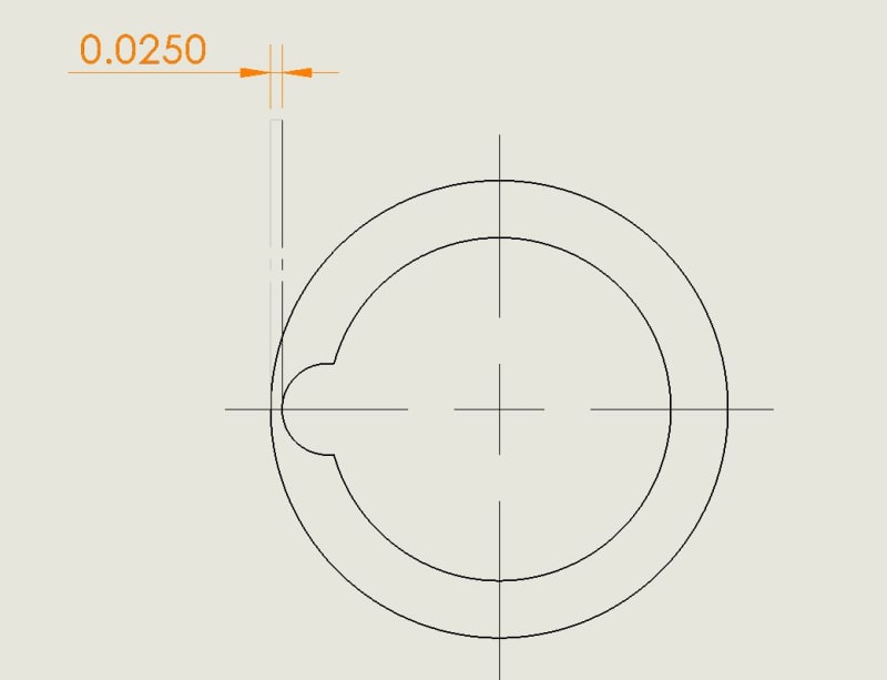
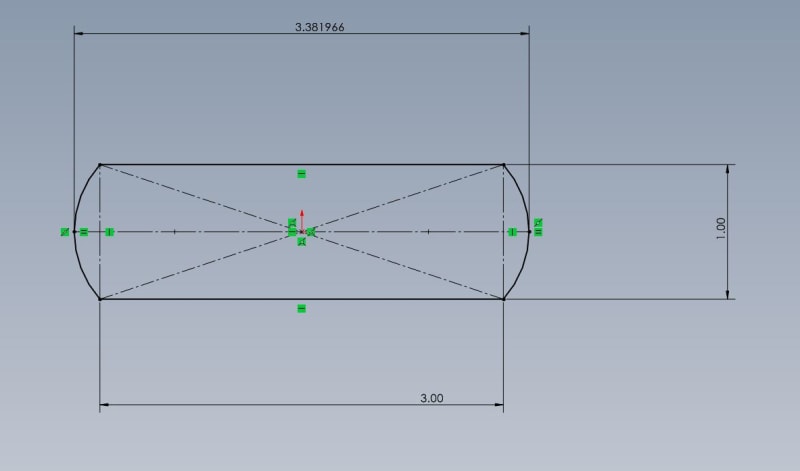
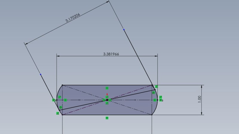
Just picture a banana shaped hole that has all local sizes equal to the LMC size and the UAME equal to the MMC size. Ignoring a relation to a datum(s) for a moment, calculate the worst-case outer boundary for that hole, given the size specification is dia. 10 +/-0.1. Is it equal to LMC=10.1?
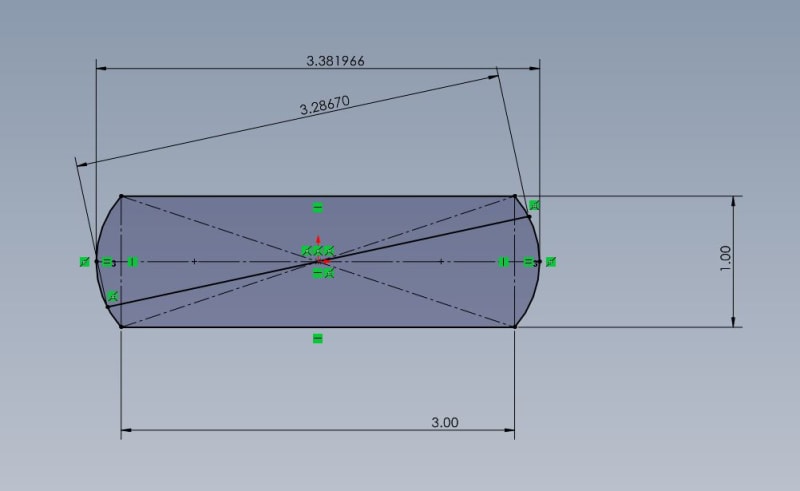
Next, plug in the locational relationship to a datum(s), say position tolerance of 0.4 at RFS, shift the feature's UAME axis to the extreme location and then calculate the size of that related outer boundary. Is it LMC+pos.tol = 10.1+0.4 = 10.5?
Burunduk said:
The likelihood argument is not my main argument. The argument is that tolerancing at LMC suffers from the same problems as RFS, especially per the axis interpretation, which is a legitimate method of evaluation. Even if surface interpretation takes precedence in case of conflict, no one is required to double-check the axis evaluation by examining whether the surface doesn't violate the VC.
You seem not to deny that an axis inspection per an LMC requirement would not prevent the violation in the case which you described.
I fully agree with this and that is why my belief for some time has been that the standard should introduce a way to graphically distinguish between the surface and axis method on the drawing. For example, the current specification method would impose the axis method only will all its geometrical inconveniences, but if someone wanted to impose the surface method it could be done for instance by using a FCF that would directly specify the size of the virtual condition boundary that shall be protected. ISO already has this allowance, but - unlike ASME - they don't have a problem with the interpretation duality because they don't define the axis interpretation for tolerances at MMC(MMR) or LMC(LMR) in their standards.
Burunduk said:
BTW, would you agree that for MMC and preserving clearance for assembly, the only advantage of MMC over RFS is the additional allowance, and not the ability to maintain the worst case boundary?
It's not the only advantage of MMC, but from the perspective of maitaning the worst case (inner) boundary I agree there is no difference. Still, this doesn't make the math correct on the other side of the feature.
Burunduk said:
It is generally considered that if the manufacturer prefers the more restrictive RFS measurement over the sometimes more complex MMC/LMC evaluation (especially in the case of LMC where no physical gages can be used) it is safe to inspect at RFS, because all bad parts will be rejected anyway, even when the tolerance is specified at LMC or MMC. The same thing applies for datum features referenced with material boundary modifiers. Do you disagree with that approach?
No, I don't, but on the stack-up analysis level it's a different story because the person doing the stack-up should consider a risk behind not including the effect of form error for tolerances at RFS. In most cases, the risk is low, as you said, and so the stack-up won't have that effect included. However, in such case not showing it is not equal to always being on the safe side.