Continue to Site

Eng-Tips is the largest engineering community on the Internet

Intelligent Work Forums for Engineering Professionals

  • Congratulations waross on being selected by the Eng-Tips community for having the most helpful posts in the forums last week. Way to Go!

Minimum Stirrup Spacing - CSA A23.3

Status
Not open for further replies.

Baffled Engineer

Structural
Jul 27, 2018
62
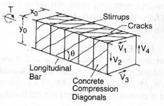
I have a 10"x24" concrete grade beam with 10M stirrups @ 14" o/c, 2-20M bars T&B, 1-1/2" clear cover.

My loading includes strong and weak axis shear plus a torsional load, and I need to have the minimum stirrup for capacity and my Tf>0.25Tcr.

According to C11.3.8.1. the max spacing for stirrups is 0.7dv or 600mm, and in C11.3.8.3 if Tf>0.25Tcr, this minimum spacing shall be reduced by 1/2.

My question is which dv do I use? Will it be the shear depth of the weak axis (dv=7.2")? It would make the maximum stirrup spacing allowed to be 2-1/2" o/c which seems overkill. If I use the dv for strong axis (dv=20") the max stirrup would be 7" o/c.

I do require the stirrup reinforcement for the strong axis since the Vf exceeds Vc in strong axis, but my weak axis shear is smaller than Vc for weak axis and won't theoretically require stirrup reinforcement. Should I be using a dv value of between 7.2" and 20" since there's an interaction between the two shear force vectors?
 
Replies continue below

Recommended for you

If I had a beam that size that needed stirrups, I'd upsize the beam so it didn't. The labor to put in all those stirrups will cost more than the extra concrete, especially if you have to go to 2 1/2" spacing. You'll also have a heck of a time getting concrete in around all that steel.
 
Sorry I forgot to mention its existing already and I'm just checking someone else's work.

The grade beam is supporting a pre-eng moment frame column and the vertical and horizontal reactions are quite high ~250kN gravity and ~150kN horizontal kickout. The torsion comes from a 9.5" eccentricity due to the fact that they offset the grade beam with the centre of the columns using a corbel. The column is anchored with 2-25M hairpin reinforcement into a 6" slab-on-grade to resist the kickout force but not all of the lateral force are transferred to the hairpins and some go into the grade beam and piles.
 
That sounds questionable from a deflection compatibility standpoint. For anything but hilariously stiff piles, it seems like that slab would have to tear our before the pile can move enough to take loads.
 
Sounds to me like you are clutching at straws. If the ties and slab are not good enough, the piles, assuming a single pile at each column, won't help much, and neither will the 10" wide grade beam. And you can't just add the differing contributions, as failure would occur in series rather than parallel.

Why are you mixing your units? kN and " don't belong in the same sentence.
 
TLHS thanks for your input. I understand the deflection compatibility issue, but what I'm trying to do is give the SEOR the benefit of additional supports he can potentially get so if the grade beam fails he can't argue otherwise.

As of now, if all the lateral force transfers to the hairpins (which is how it was probably designed to cancel the reactions from the other side of the frame), the grade beams will be over-utilized in torsion due to the eccentricity of the gravity loads alone.

But, if some of the lateral force gets transferred to the piles, the applied torque on the grade beams actually gets reduced since the resultant torque from the kickout force on top of the grade beam counteracts the torque from the eccentric gravity load, but there will be weak axis bending & shear in the grade beam. Hence, I wanted to check the grade beam if it passes capacity and code requirements with this configuration.

 
Thanks hokie66. There is a 16" dia. pile on each side of the column 2' away. The torque from the eccentric gravity load has to be resisted by the piles since there's no other explicit way to get it out of the system.

I also have it so that there are lateral supports on top of the grade beam from the 6" slab-on-grade, so if the grade beam ever tries to torsionally rotate it would lean on the slab-on-grade at some point. This probably would be questionable as well since there's a 1/2" bond breaker b/w the slab and the grade beam but I'm doing it for the benefit of the SEOR.

As for the units, my university thought me using mostly metric but at work we usually use imperial in our drawings. My stress/force calcs are always in metric and I always convert imperial dimensions to metric to do my calcs. The imperial dimensions are just easier for me to visualize since my previous job involve building pre-eng trusses in imperial units. You are right though, they should never appear in the same sentence and I'm working on being consistent with one unit system to avoid potential errors.
 
Not sure I completely understand, but focusing on the lateral thrust, are you concerned that the slab is not capable of resisting the force? I have never been a proponent of using a slab on ground as a tension tie, but it is often done. You stated you have two hairpins, thus 4-M25 bars. 150 kN tension only results in about 80 MPa on the bars, so if they are lapped with enough reinforcement in the slab, it should theoretically work, with probably some cracking.

Perhaps a sketch would help to understand the grade column/beam/corbel/pile connection.
 
Going back to your original question, the stirrup spacing should be based on the 10" grade beam dimension rather than the 24" dimension. That, as a logical consequence of our envisioning concrete beam torsion as a three dimensional truss model. An argument could be made that the "top flange" of the three dimensional truss might be exempt from this requirement by virtue of the continuous lateral restraint that it receives from the slab. I've done this myself for interior beams where I wanted to resist torsion but did not want to provide closed stirrups. Your situation would be a bit sketchier given that you have slab on only the interior side of the beam and would be relying on reinforcement for lateral restraint of the exterior side of the beam.

c01_eixutn.png
 
Status
Not open for further replies.

Part and Inventory Search

Sponsor