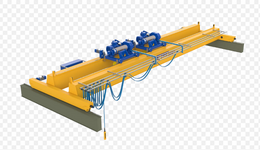
I am trying to design a double girder overhead crane with a span of 40 meters. 2 trolleys are placed on top.
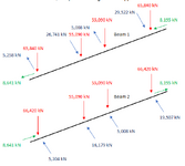
I am calculating the skewing forces for the trolleys using EN15011 or EN1993-3. The skewing forces are as stated below. (see attached image for clarification on how the forces apply to the crane girders)


These skewing forces push the crane girders towards eachother, or away from eachother.
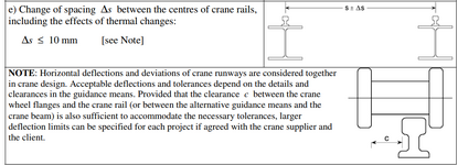
In 1993-6 the following maximum deflection is given between the centre of rails. This is given for the supporting beams of the entire crane, but might also apply for the trolleys, because these have to travel across the rails aswell?

However if i use these tolerances each beam has a maximum allowable deflection of 5mm. With a span of 40m this is a tolerance of L/8000. This seems very strict. My girder requires almost the same moment of inertia around its weak axis as its strong axis. This does not seem right?
The note states that we can increase clearance c. However the skewing angle is limited to 0,015 rad, and this will also increase the skewing forces.
How could i continue? Should the L/8000 deflection limit be applied, or is there a more appropriate tolerance?
I am calculating the skewing forces for the trolleys using EN15011 or EN1993-3. The skewing forces are as stated below. (see attached image for clarification on how the forces apply to the crane girders)


These skewing forces push the crane girders towards eachother, or away from eachother.
In 1993-6 the following maximum deflection is given between the centre of rails. This is given for the supporting beams of the entire crane, but might also apply for the trolleys, because these have to travel across the rails aswell?

However if i use these tolerances each beam has a maximum allowable deflection of 5mm. With a span of 40m this is a tolerance of L/8000. This seems very strict. My girder requires almost the same moment of inertia around its weak axis as its strong axis. This does not seem right?
The note states that we can increase clearance c. However the skewing angle is limited to 0,015 rad, and this will also increase the skewing forces.
How could i continue? Should the L/8000 deflection limit be applied, or is there a more appropriate tolerance?
