Eng-Tips is the largest forum for Engineering Professionals on the Internet.

Members share and learn making Eng-Tips Forums the best source of engineering information on the Internet!

  • Congratulations JStephen on being selected by the Eng-Tips community for having the most helpful posts in the forums last week. Way to Go!

Mat Foundation Can Be Thinner, Why Not? 1

Status
Not open for further replies.

KootK

Structural
Joined
Oct 16, 2001
Messages
18,757
Location
CA
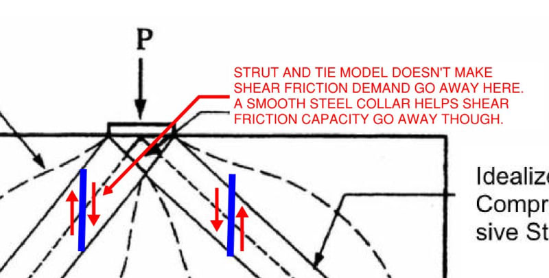
Why not?? Because the concept is deeply flawed, that's why. At the least, that's how it has appeared to me over the last 2+ years that I've been contemplating this.

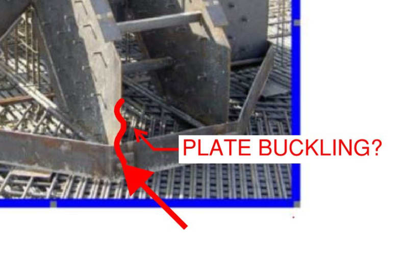
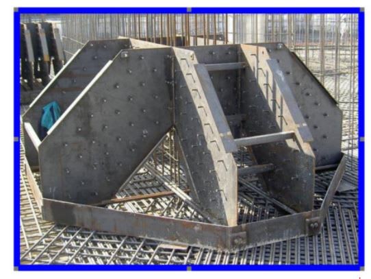
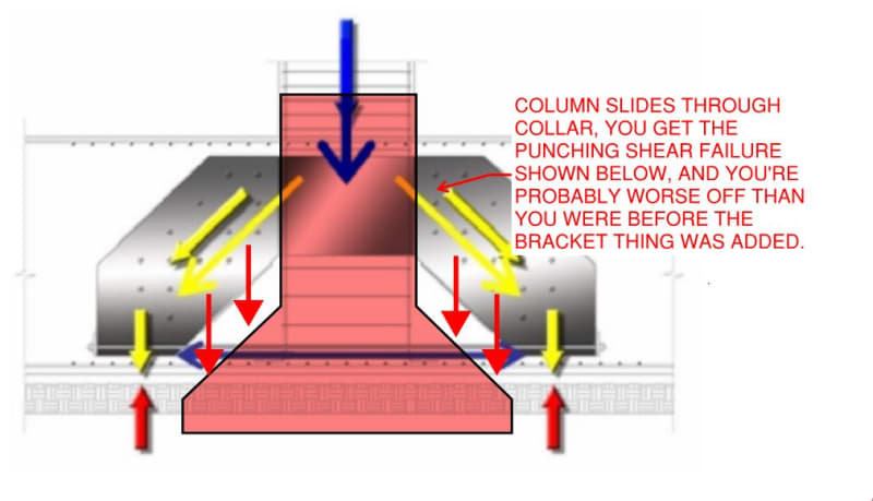
Please refer to the attached article and the sketches shown below. This is an innovation in foundation punching shear design that's been put into practice on some significant buildings.

What am I missing here?

c02_lyvmlx.jpg


C01_qshan9.jpg

 
If it doesn't work as intended, it would be a helluva thing to repair...

Rather than think climate change and the corona virus as science, think of it as the wrath of God. Feel any better?

-Dik
 
Right? The paper that I attached describes some validation testing. However, I worry that validation testing setup directed the vertical load straight into the steel ring in a way not reflective of how a full scale column joint would be expected to behave.
 
They took all that time to weld 200 shear studs to the sides of it...why not add a bunch more to the inside of the collar thingy?

I don't know that it would actually solve the problem, but at least there would be something to point to and say 'theres the load path!' Right now there isn't much...
 
I don't get why someone would do that rather than a (traditional) bent bar arrangement. If you are having to put in a monster like that......most likely you are going to have shear problems beyond it's influence.
 
Daywalker said:
...why not add a bunch more to the inside of the collar thingy?

Yeah, internal studs or friction was the best that I could come up with and I don't see the studs. And, even then:

1) I imagine you'd be looking at a few studs for an 80 story building column and;

2) One would need much larger reproductive organs than I have to rely on bare surface friction.

WARose said:
......most likely you are going to have shear problems beyond it's influence.

Exactly. I drew what I thought the governing mode would be but, you're right, one would seem to have another failure surface to deal with not so far from the original. I'm not sure how much to read into their STM model but the location of the ground reaction arrows sort of implies that spread isn't actually required beyond? My understanding is that this originated in the NY highrise market. In NY everything's on bedrock so maybe that's legit. At the least, it might explain why these things aren't collapsing.

 
Corollary to my main concern but still...

C01_q2vxri.jpg
 
Corollary to my main concern but still...plate buckling?

Yeah, I'd wonder about that too. If I was doing it....it would be checked as if it wasn't being braced by anything while embedded.
 
Originated in NY you say? The Mob probably took over some steel mills and politely suggested as much steel be added into structures as possible.
 
I can't find the paper published in any peer reviewed journal, Using it as a reference for an alternative solution would be problematic, could have another punching shear solutions that hasn't been fully vetted. I

To solve the load path, I would want to weld a crussiform between the corners under the column maybe add some studs to this.
 
Part of my interest in this is that it dovetails into my thoughts on shear friction: Shear Friction: Where and When?. In the linked thread, and many others, I developed my theory that shear friction is alive and well as a necessary mechanism anywhere that concrete is exposed to a transverse shearing force component. When I look at the strut and tie models in the linked paper on this, what I see is a failure to appreciate this.

C01_m0hzu1.jpg
 
Think strain compatibility...not just with regard to rebar and concrete, but with all components...particularly the steel monstrosity.

Kootk....agree with your sketch...the steel frame is useless.

 
KootK said:
What am I missing here?

Probably..... that someone is brave enough to put their name in this "innovation". Love to see the actual performance. If they designed this with an SF of 3.0 it probably might work.
 
A concrete pedestal under each column could reduce mat thickness, but not the depth of excavation.

BA
 
I would be very concerned. It’s completely counter intuitive.

As above, if there were studs inside the collar then i’d give it some credit, but even then i can’t imagine it would achieve anything remotely close to the degree of shear connection required.

Is this actually being used around the place?!
 
A contrarian view, if I may. I think the concept has legs, but probably needs more testing for it to be codified. The test results look promising, and I think the setup does resemble real world practice. The whole assembly is cast into the mat, then the column goes on top, and the 'collar' serves to confine the concrete within. If sliding through is still a concern, providing a bit of slope to the sides of the collar would help.
 
If it's all encased in concrete... buckling would be one of the least things I would be concerned about...

Rather than think climate change and the corona virus as science, think of it as the wrath of God. Feel any better?

-Dik
 
To be honest I'm confused I would be thought that such an arrangement wouldn't work if appropriately designed. Another way of thinking of it is just a different way of arranging your reinforcement. The method of failure proposed by Kootk in the first post could occur then it could also occur without the fabricated assembly. From what I can see there is still horizontal shear reinforcement in the top layer.

It's stated goal isn't to surpass the performance of heavily reinforced mat, it is to achieve similar performance with a design that has less site work. As to the economies to be gained that would depend on the labour costs tradeoffs.
 
Human, while i could potentially agree with that (that the studded fins are just an alternative to punching shear reinforcement Links), I think the collar lets the whole system down by creating a slip plane between column and the very foundation it wants to punch through.

This would have some chance if it didn’t have the collar.
 
That node in the left side of figure 4 has a plate to carry the weight - this has an open hole.

The model in fig. 13 shows load applied directly to the steel; again, the actual use has a big hole for the load to pass through. The test diagrams appear to show a substantial steel bridge across the test item, plugging that hole.

The one-way modules look more realistic a load spreaders; the two-way evaluations look overconfident.

Why would the test article not include a section of column as that is the way loads are introduced?

How To Ask Questions The Smart Way
 
Status
Not open for further replies.

Part and Inventory Search

Sponsor

Back
Top