Tek-Tips is the largest IT community on the Internet today!

Members share and learn making Tek-Tips Forums the best source of peer-reviewed technical information on the Internet!

  • Congratulations TugboatEng on being selected by the Eng-Tips community for having the most helpful posts in the forums last week. Way to Go!

Lateral load distribution to concrete shear wall and steel bracing frame

Status
Not open for further replies.

youjun

Structural
Joined
Nov 10, 2019
Messages
1
Location
AU
Question 1:
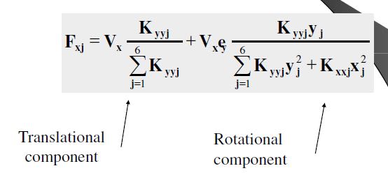
For a building with concrete shear walls and steel bracing frames. How do we distribute the seismic loads between the shear walls and steel frames? I found some notes for the distribution of forces to individual elements:

Capture_p3gvrf.jpg


I have asked some other engineers and some suggestions include:

A. Apply a unit force to the elements and this will determine the relative stiffness for the "K" variable.
B. Treat all the elements as concrete shear walls and then design the steel frames for the distributed forces.

Question 2:
When distributing lateral forces to a building with only concrete shear walls acting as the LLRS, the procedure involves determining the individual stiffness of each wall, i.e. BD^3/12. But this method seems to neglect the level of steel reinforcement within each wall? If a shear wall is more relatively reinforced, would it not be stiffer and attract more load?

Thank you in advance.
 
"If a shear wall is more relatively reinforced, would it not be stiffer and attract more load?"

Being a bridge guy, I'm not sure I understand your configuration, but I'll offer just this:

If a single loading is distributed between the steel frames and concrete wall, I believe you are correct that it will be distributed based on the stiffness of the components. However, the amount of reinforcing in the concrete should be of little consequence, since it's the total stiffness of the cross section, comprised mostly of the concrete, that will provide the stiffness. Even a lightly reinforced concrete shear wall will have a large stiffness just due to the large cross section it presents, even though it has a lower modulus of elasticity than steel.

Rod Smith, P.E., The artist formerly known as HotRod10
 

A. Apply a unit force to the elements and this will determine the relative stiffness for the "K" variable.
[red] Yes this is what is proper[/red]

B. Treat all the elements as concrete shear walls and then design the steel frames for the distributed forces.
[red]No - this over-emphasizes the relative stiffness in the steel frames (not a bad thing, but underestimates the relative stiffness in the concrete (a bad thing).[/red]

Dependent on these questions is whether the diaphragms are flexible, partially rigid or rigid.
You have to analyze the overall framing system including the relative stiffness of the diaphragm as well.

 
For question 1, I agree with JAE.

For question 2, I'd say it depends. Is this seismic or wind loading? For wind, I'm not inclined to let my wall start cracking a bunch, so neglecting any change in stiffness due to reinforcing (at least for a low to mid rise building) probably won't get you into trouble. For tall buildings and seismic (cyclic) loading, a more detailed analysis may be warranted.

This topic isn't new to the forum: thread507-255861
 
The job should be getting very interesting, when you need to evaluate Ie/Icr of reinforced concrete walls for every case.
 
If a shear wall is more relatively reinforced, would it not be stiffer and attract more load?

So your initial analysis would probably start with the simple wall stiffness (neglecting reinforcement) because the key to the analysis is the RELATIVE stiffness between the walls....not necessarily the actual stiffness because you are looking for relative stiffness that affects the load distribution between walls.

Once you run your first analysis, and design the walls based on that with adequate reinforcement, the next step is to now adjust those relative stiffnesses to account for possible differences in reinforcement and the re-run. The second/supplemental runs will alter the distribution a bit due to the rebar differences and allows you to re-check the design.

ACI 318 (318-11) suggests this concept in section 10.10.4.1 where they state that initial assumed semi-cracked stiffnesses of beams, columns and walls can be initially presumed but then "The dimensions of each member cross section used in the analysis shall be within 10 percent of the dimensions of the members shown on the contract documents or the analysis shall be repeated."

 
Again, I'm not familiar with this type of design, but it seems the stiffness of the concrete (uncracked, "semi-cracked", or fully cracked) would depend on the source and magnitude of the loading. For wind loading, I would expect an assumption of an uncracked section, with the concrete section of the shear walls sized to validate that assumption, since you wouldn't want it to crack under repeated loading cases. For one-time loading, such as the design seismic loading, I would think the "semi-cracked" or fully cracked assumption would be appropriate. To take the simple and conservative approach, you could design the steel bracing using the the assumption of a fully cracked concrete section for the load distribution and design the concrete based on the assumption for stiffness of uncracked concrete (envelope the design).

Rod Smith, P.E., The artist formerly known as HotRod10
 
Status
Not open for further replies.

Part and Inventory Search

Sponsor

Back
Top