A couple things to note...
This seems to be largely a repeat of many of the same things discussed in the following thread: thread2-480875
I fully agree with many of the comments above regarding fictitious stress artifacts sometimes resulting from FEM (as I noted in the other thread). However, I will also note the same caveat I did there.
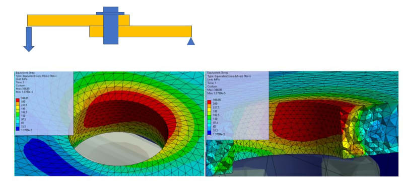
Before "writing off" those peak stresses as non-problematic, it is pretty important to try to understand why they are appearing in the first place. How exactly are your joints modeled in the FEM (are the peak stresses the result from RBE "attachment points" or something else model related? Or is there something going on with the way you've loaded the model or constrained it?
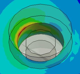
Based on your description and FBD above - "It is similar to a lap joint under bending condition"... first off, I'm having trouble thinking of where that would be actually implemented as a design decision. But, that is a situation where you could very well in fact have a lot of eccentricity. Because of the rotation of the plates and the way the fastener impinges on the hole inner surface, you will have a highly skewed effective bearing area. This will cause the bearing load to be distributed over a much smaller area, and you could actually see pretty high stresses there.
Last, I will also note, that once you start running a non-linear analysis, writing margins becomes less about Ftu and more about strain. Remember, Ftu is usually higher than the rupture stress for ductile materials. So if you are running this non-linearly, where the stress will locally redistribute once it passes Fty, you actually want to write a strain margin. You should check that the strain at your ultimate load is less than the rupture strain. You should also be checking the scale of the plastically deformed material to make sure it is reasonable, and probably also check the maximum displacement as well.
Keep em' Flying
//Fight Corrosion!
") )
)