N
Nick Brenn
Guest
I am working to generate a more accurate 3D model of a circuit board, using 3D components downloaded from supplier websites.
Since I am new to PTC Creo 3.0 (I have an electrical background), I am having a difficult time replacing the original parts with the parts that I downloaded from the supplier's websites.
Here is my process, that I learned from some instructional videos online:
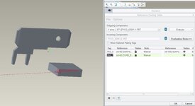
View attachment 6780
I chose the proper references, and then hit Apply and OK.
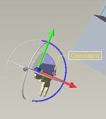
The issue that I am running into, is, when I hit OK, the component is not being replaced in the same location as the original component. It is being placed off to the side of the circuit, with the movement capabilities added to it (I am within Component Placement). And when I hit the Green check mark, after dragging it to my desired location, it disappears.
View attachment 6781<- the component isn't in the location of the component I wanted to replace it with.
Any help is greatly appreciated
Since I am new to PTC Creo 3.0 (I have an electrical background), I am having a difficult time replacing the original parts with the parts that I downloaded from the supplier's websites.
Here is my process, that I learned from some instructional videos online:
- Select the component that I wish to replace.
- Select Operations -> Replace
- Since I am replacing, say, a 3D rectangle with an actual component, I select "Unrelated Component"
- I selected the component that I am looking to replace.
- I chose "Edit Reference Table". Question 1: What am I supposed to do with Tag1?
View attachment 6780
I chose the proper references, and then hit Apply and OK.
The issue that I am running into, is, when I hit OK, the component is not being replaced in the same location as the original component. It is being placed off to the side of the circuit, with the movement capabilities added to it (I am within Component Placement). And when I hit the Green check mark, after dragging it to my desired location, it disappears.
View attachment 6781<- the component isn't in the location of the component I wanted to replace it with.
Any help is greatly appreciated