Mhrob
Mechanical
- Jan 7, 2022
- 4
Hello all. First time post here. Soon-to-be graduated engineer currently in an internship.
So I am working on preparing drawings for some brackets I’ve designed, and I have a request to change something from management that I am not sure how to go about.
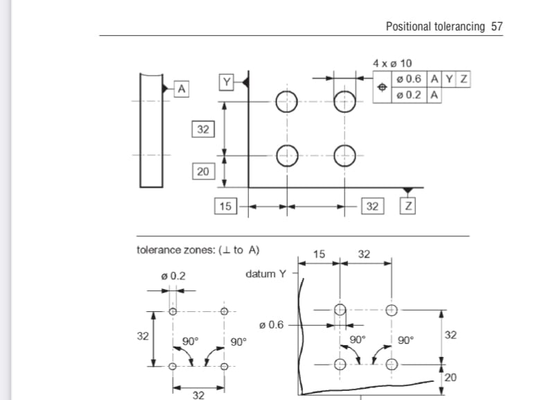
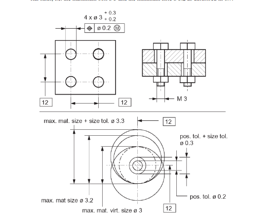
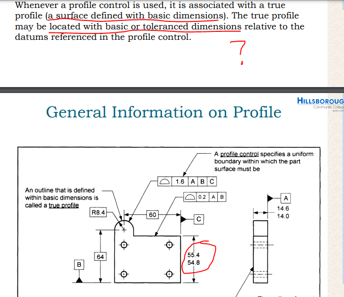
For a composite position tolerance (in ASME), I am used to something similar to the image shown below. 3 datums in the upper segment with TEDs tied to the datums that controls movement of the pattern AS A UNIT, and then a lower segment that further refines the tolerance….in this case, spacing between the individual holes and the perpendicularity to datum A (I think….)
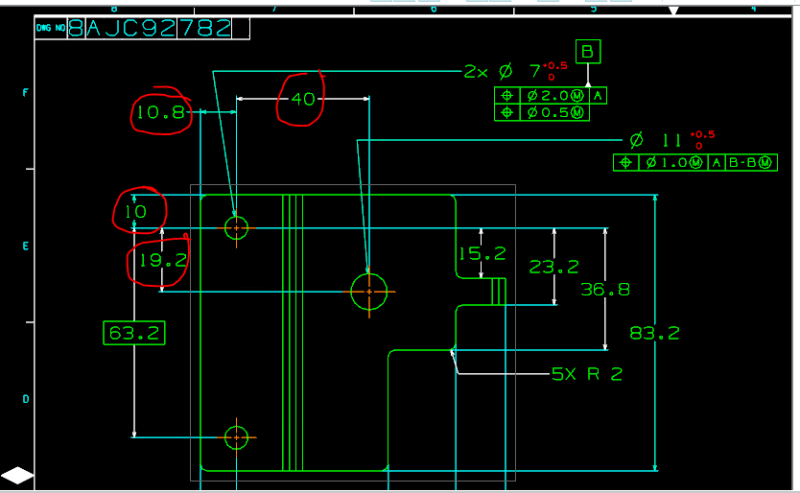
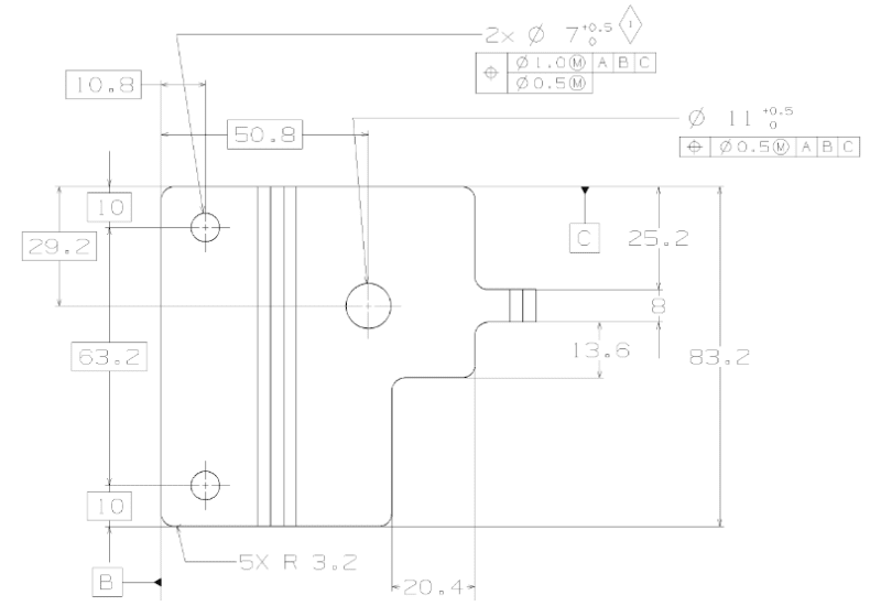
However, I have been told to make my two 7 mm hole pattern as datum B. I realize in ISO that if you have a pattern set as a datum, you put B-B in the tolerance box when referencing other feature tolerances to that…..but what about the pattern itself? How will my upper segment change now? I want to control the holes as a unit within a 2 mm zone, and then control individual spacing by using a 0.5 mm zone. But what datum now goes into the upper segment? I can’t put B-B in that can I? Because the pattern itself is datum B…..
So I am working on preparing drawings for some brackets I’ve designed, and I have a request to change something from management that I am not sure how to go about.
For a composite position tolerance (in ASME), I am used to something similar to the image shown below. 3 datums in the upper segment with TEDs tied to the datums that controls movement of the pattern AS A UNIT, and then a lower segment that further refines the tolerance….in this case, spacing between the individual holes and the perpendicularity to datum A (I think….)
However, I have been told to make my two 7 mm hole pattern as datum B. I realize in ISO that if you have a pattern set as a datum, you put B-B in the tolerance box when referencing other feature tolerances to that…..but what about the pattern itself? How will my upper segment change now? I want to control the holes as a unit within a 2 mm zone, and then control individual spacing by using a 0.5 mm zone. But what datum now goes into the upper segment? I can’t put B-B in that can I? Because the pattern itself is datum B…..
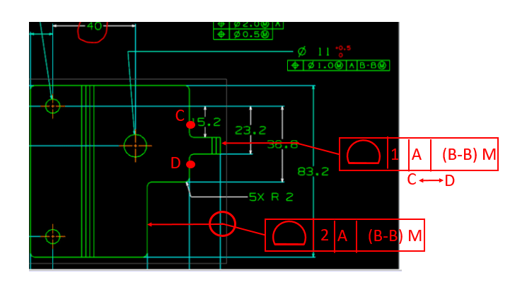
") my hand if I say something wrong), but I think you could use profile in between points C and D on the other contour in the same way as you did for the anti-rotation tab.
my hand if I say something wrong), but I think you could use profile in between points C and D on the other contour in the same way as you did for the anti-rotation tab.