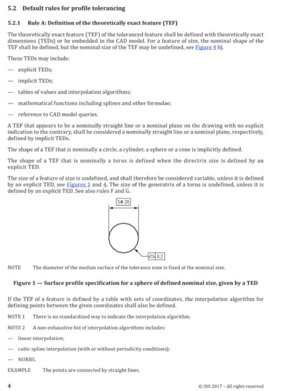
Eng-Tips is the largest forum for Engineering Professionals on the Internet.

Members share and learn making Eng-Tips Forums the best source of engineering information on the Internet!

  • Congratulations JStephen on being selected by the Eng-Tips community for having the most helpful posts in the forums last week. Way to Go!

ISO GPS - Line profile for a spine of a bent rod? 2

Status
Not open for further replies.

Burunduk

Mechanical
Joined
May 2, 2019
Messages
2,582
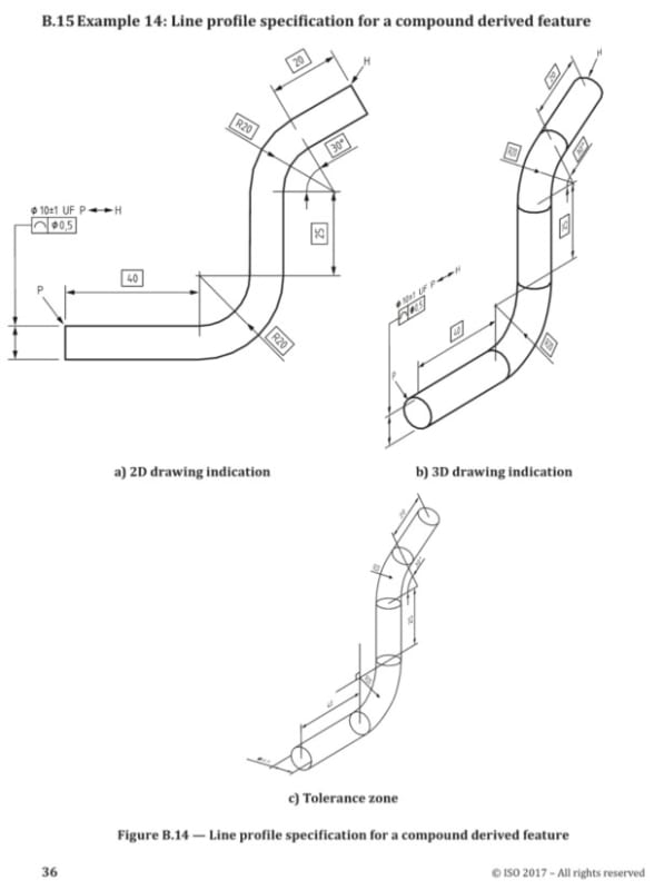
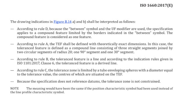
In thread1103-514448, at the last post of the thread, I saw this figure posted by Ryan and taken from ISO 1660. It surprised me a lot because I have never seen a diametric tolerance zone for profile of a line applied to a resolved geometry (spine?) of a feature of size (associated with the diameter dimension). I do not have a copy of ISO 1660, but I haven't found anything similar in ISO 1101-2017.

Is anyone here familiar with it and could maybe elaborate a bit about where exactly and how such a control is defined in the ISO GPS standards?
 
Burunduk said:
I have never seen a diametric tolerance zone for profile of a line applied to a resolved geometry (spine?) of a feature of size (associated with the diameter dimension).
I work with ISO quite a bit, and I can say that I have never seen a diametric tolerance zone for profile at all, regardless of it being a spine, FOS, or any other thing.
I'm interested to hear a full explanation.
 
And I already know who's opinion is needed here......
I am waiting for his valuable and pertinent views on the raised issue.
 
OP said:
. It surprised me a lot because I have never seen a diametric tolerance zone for profile of a line applied to a resolved geometry (spine?) of a feature of size (associated with the diameter dimension).

Per what I learn from people here on the forum which have more knowledge than I do in ISO GPS is that the characteristic that the profile applies to is pure cylindrical shape of the feature disregarding the size specification.

So this specification is applied to a derived feature and the integral feature does not need to be defined with TED's (diameter of the feature is plus-minus)

Maybe a question could be added: can we add MMR too?
I would think so.....then the geometrical tolerance would change from derived feature to a requirement applied to a surface feature....I guess.

 
Burunduk

This is indeed a good question for people with an ASME background, I hadn't noticed that before. Just providing some of the relevant content of the standard, and I am also looking forward to further interpretation as mentioned by greenimi.

2024-07-22_103143_deez8p.jpg


2024-07-22_103244_bw78wt.jpg


2024-07-22_103320_bqprr2.jpg


2024-07-22_103946_mgwlcy.jpg


2024-07-22_103457_tuipqf.jpg


2024-07-22_103541_tmzgir.jpg
 
In response to Burunduk's enquiry on where this type of control is defined - The example in Figure B.14 is a combination of a compound feature per ISO 1101 section 9.1.4 and the application of Rule C of ISO 1660 as posted above. The tolerance limits are a tube formed by an infinite series of spheres around the derived centreline of the compound feature.

Ryan.
 
SeanonLee and Ryan,
Thank you for your high quality answers.
As SeasonLee indicated, having mainly ASME background I will have to let it sink in.
 
Status
Not open for further replies.

Part and Inventory Search

Sponsor

Back
Top