bromden
Civil/Environmental
- Jul 25, 2003
- 2
I'm designing a new 20 GPM deep groundwater well in an area with shallow bedrock. I'm comfortable with design of the well development (I'm relying on a senior hydrogeologist for that), but the topography and bedrock has presented an interesting challenge for the 1000ft long, 2 inch diameter raw water pipe from the well to the treatment facility. Between the well and the treatment facility there is a peak. The topo ranges as much as 20 ft.
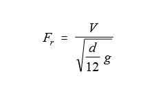
The hydraulic grade line should stay well above the pipeline, but I'm not sure how best to eliminate concerns about air binding up the pipeline at the high point. One colleague is suggesting the line is small enough and the pressure high enough (60 psi) that any air that comes out of solution or is left during fill of the line would just get pushed along to the plant, which wouldn't be a bid deal. I'm not convinced, but I've never had to put such a small line in for this great of a distance with this much change in elevation. I've certainly never tried to put an ARV on a 2 inch line.
So I've looked at a few options - relocating the well, changing the alignment, decreasing/increasing the size of the pipe, horizontally drilling the pipe from well to plant with a continuous slope, etc. but it's bothering me that this is just a little line that we should be able to simply trench through with 3 ft of cover. Is there any basis in the assertion that air wouldn't collect and restrict flow?
I'd appreciate any thoughts.

