Continue to Site

Eng-Tips is the largest engineering community on the Internet

Intelligent Work Forums for Engineering Professionals

  • Congratulations The Obturator on being selected by the Eng-Tips community for having the most helpful posts in the forums last week. Way to Go!

How to identify "mechanically" induced vibration and acoustics noise?

Status
Not open for further replies.

onemilimeter

Electrical
Jul 25, 2009
54
Hi,

My background is in electrical engineering. I wish to analyse the vibro-acoustics of a 3-phase permanent magnet brushless machine. I'm aware that vibration or acoustics noise can be generated "electromagnetically" (due to MMF, airgap field, etc) or/and "mechanically" (e.g. misalignment, eccentricity, unbalanced load, bearing, brush/commutator, etc.). As I need to analyse the vibro-acoustics of the PM motor at various loads, the PM motor must be attached to a DC machine (armature winding connected to a variable resistive bank), which acts as a load during testing (see attached image). I'm aware that, in practice, it is very difficult to avoid misalignment and eccentricity. In other words, there will be some degrees of misalignment or eccentricity in real world setup. As I'm interested only in "electromagnetically" induced vibrations and acoustics noise, I wish to distinguish "electromagnetically" induced vibrations and acoustics noise from that of mechanically induced.


I've the following instruments: dynamic signal analyser, PCB accelerometer, and sound pressure meter. The accelerometer is attached (using wax) to the motor under test.


Questions:
[Case-1] The PM motor is not excited, i.e. the winding terminals of the PM motor are left open. In this case, the PM motor is driven by the DC machine (i.e. the DC machine acts as a motor now), e.g. at 1000rpm (rated speed of the PM motor). What is the information that we can extract from the vibration reading measured by the accelerometer? Can we use this experiment to identify "mechanically" induced vibrations?

[Case-2] If the winding terminals of the PM motor are connected to a 3-phase resistive load (in such a way that the current flows in each phase winding is the rated phase current of the motor), and like in Case-1, it's driven by the DC machine at 1000rpm, what is the information that we can extract from the vibration reading measured by the accelerometer?


As I'm a novice in vibro-acoustics test, please correct me if any of my comment is wrong. Please also kindly suggest if you have better options to identify "mechanically" induced vibration and acoustics noise of my experimental setup.


Thanks
 
Replies continue below

Recommended for you

[Case-1] The PM motor is not excited, i.e. the winding terminals of the PM motor are left open. In this case, the PM motor is driven by the DC machine (i.e. the DC machine acts as a motor now), e.g. at 1000rpm (rated speed of the PM motor). What is the information that we can extract from the vibration reading measured by the accelerometer? Can we use this experiment to identify "mechanically" induced vibrations?
I would say yes. Vibrations at 1x running speed measured on the PM motor are certainly not electrical origin from the PM motor since it is deenergized. One exception might be electrical related vibration on the dc motor (such as rectifier ripple frequency) which might be transmitted to the PM machine.

[Case-2] If the winding terminals of the PM motor are connected to a 3-phase resistive load (in such a way that the current flows in each phase winding is the rated phase current of the motor), and like in Case-1, it's driven by the DC machine at 1000rpm, what is the information that we can extract from the vibration reading measured by the accelerometer?
First step is to look at the pattern of the vibration (primarily the frequencies, also the directionality and possibly the time waveform) to try to discern the nature of the vibration. If vibration is at running speed I would think usually mechanical. Vibration at number of poles times running speed would likely be electrical. Bearing fault frequencies are mechanical. Vibration which is highly directional is usually amplified by mechanical resonance.

=====================================
Eng-tips forums: The best place on the web for engineering discussions.
 
Time waveform which resembles impacting (sharp increase followed by oscillating decay) is usually mechanical. The repetion rate of the impact is another clue and ties back to the spectrum (periodically repeating impact corresponds to series of harmonics of impacting frequency).

=====================================
Eng-tips forums: The best place on the web for engineering discussions.
 
It's not that quite straightforward. A "de-energized" PM motor will act like a generator when mechanically spun. The generated EMF can potentially induce mechanical effects.

TTFN

FAQ731-376
 
I agree. The associated magnetic vibration would be at twice the electrical frequency.

=====================================
Eng-tips forums: The best place on the web for engineering discussions.
 
Again the key is to look for the frequencies. I didn't mention the possibility of twice electrical frequency in the case 1 discussion but if twice electrical frequency vibration is seen in those conditions it very likely leads to an electrical source. Likewise the 1x running speed vibration I discussed in case 1 very likely leads to mechanical source.

=====================================
Eng-tips forums: The best place on the web for engineering discussions.
 
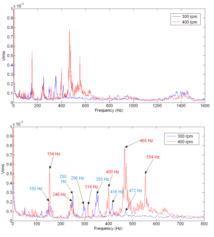
I did several tests as follows. The PM motor was driven by the DC machine at 300rpm (or 300/60=5Hz) and 400rpm (or 400/60=6.67Hz). Measured results are given in attached image. It looks to me that most vibration peaks found at frequencies much higher than the fundamental 1X running speed. Besides, vibration peaks are found around 250Hz on both 300rpm and 400rpm vibration spectrum, which, in other words, these peaks do not depend on rotating speed. Would you please help me to explain the results?

To electripete:
You wrote: "...First step is to look at the pattern of the vibration (primarily the frequencies, also the directionality and possibly the time waveform)..."
May I know what does "directionality" mean in your statement?


Thank you very much.

DrivenByDCMotor.png
 
 http://files.engineering.com/getfile.aspx?folder=e789a263-32ca-4dc6-a439-e9afd1aa9993&file=DrivenByDCMotor.PNG
Additional information...
The DC machine is a shunt DC machine. It's field and armature winding are connected to two different regulated DC power supplies.
 
Directionality = comparison between directions, usually horizontal and vertical measurements on a horizontal machine. If vib at a given frequency is much higher in horizontal direction than vertical, we often suspect resonance in the horizontal plane at that frequency.

How may poles does the PM machine have?

=====================================
Eng-tips forums: The best place on the web for engineering discussions.
 
and where was the vibration collected...on the bearing housing?

And what are the units of velocity used?

=====================================
Eng-tips forums: The best place on the web for engineering discussions.
 
Thanks electricpete.

The accelerometer is placed on the PM motor body as shown in attached experimental setup. I use PCB accelerometer 303A03 and you may find its specs here:


The PM motor has 12 slots and 10 poles (or 5 pole-pairs). By the way, which "velocity" do you mean? The Y-axis of results shown in my previous post were not scaled to the actual units.

DrivenByDCMotor.png


Thank you very much
 
In my experimental setup, the PCB 303A03 accelerometer and the Impact Hammer are connected to PCB 480C02 Power Units (
Kindly refer to the spec sheet of 480C02 as well as 303A03 ( The discharge time constants of 480C02 and 303A03 are >10s and 1s respectively. What do these discharge time constants mean? How will these time constants affect the vibration measurement?
 
Please kindly help me to interprete the results. I really have no clue on how those spikes come about.
 
At 300 rpm (5hz), a 10-pole machine generates 25hz voltage and current. (25 hz is frequency of output of the generator). The associated forces vary at twice the electrical frequency (since magnetic force is unidirectional varying between 0 and max twice per electrical cycle) which would be 50hz.

The pattern of harmonics of 50hz are seen in the blue (300cpm) spectrum: 150, 200 (not labeled), 250, 300 (labeled 296?), 350. These are very likely electrical.

I don't quite understand the 416 and 472. Could be lots of things. Do you happen to have the bearing part numbers?

You lost me when you started talking about hammer. I assume these are running vibration tests, not impact tests. Where does the hammer fit in?

=====================================
Eng-tips forums: The best place on the web for engineering discussions.
 
Thanks electripete.

First of all I wish to apologize for mentioning "Impact Hammer" in my last post in this thread. I did carry out several Impact Hammer tests (please refer but they are nothing to do with the test mentioned in this thread.

The test results shown in my previous post were obtained based on the test setup and procedure as described in Case-1 (please refer to my first post of this thread), except that now the DC machine runs at 300rpm and 400rpm. As the terminals of the PM motor (which is driven by the DC machine) are left open, I suppose the PM motor does not produce any current. Unfortunately, I do not have the bearing part numbers. As the DC machine is a brushed DC shunt wound machine, do you think the brush/commutator assembly will contribute to the vibration spectrum shown above?

By the way, is there any vibration source that does not rely on motor speed (those spikes marked by YELLOW circle in the results)?

Thank you very much
 
The part number of bearings used in the PM motor is "6001-ZZ C3". However, I could not find the part number of bearings for the DC machine.
 
-- SOS -- Please help me to interpret the experimental results... Thanks.
 
Status
Not open for further replies.

Part and Inventory Search

Sponsor