Continue to Site

Eng-Tips is the largest engineering community on the Internet

Intelligent Work Forums for Engineering Professionals

  • Congratulations The Obturator on being selected by the Eng-Tips community for having the most helpful posts in the forums last week. Way to Go!

How to calculate forces from an object bouncing 3

Status
Not open for further replies.

Jimbob218

Mechanical
Jun 1, 2016
2
Hello all,

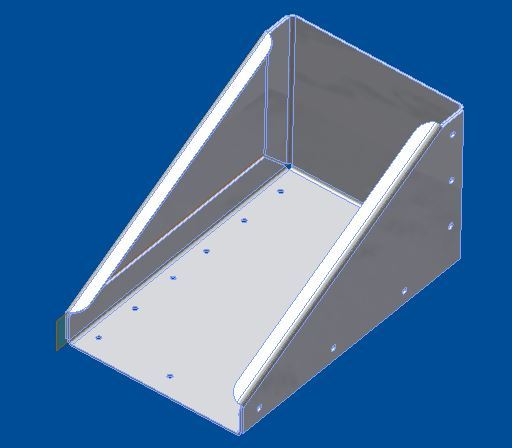
I am done with the 1st half of my BSME so I have touched on this type of thing but as for the actual application I am having trouble. I am trying to design a bracket to hold a small (110 lb) outboard motor on the back of my boat. Right now I have it modeled with .125'' thk 6061-T6 mostly because we have a large sheet of it at my work I can use for free, but I want to make sure it will hold up. I want to figure out what forces will be acting on the bracket as the motor bounces around while going over waves or while on the trailer.

Thanks in advance for your help!

Capture_irsiti.jpg
 
Replies continue below

Recommended for you

Before getting into the dynamics, I recommend you get a copy of the Aluminum Association Manual which covers aluminum design. Check on the requirements for b/t and h/t, etc.
This will also introduce you to the mandatory lifetime engineering requirement of spending large sums for codes and standards that you will have to replace every three years.

ps: Your question is too broad.
 
One thing to know is that it is better to start off with an arrangement drawing - showing the relative positions of the boat, the motor, and a rough idea of what the bracket will be like. Then you can add the masses and forces that are expected. Then come the reaction loads, and from the reaction loads the final structure can be started.

As it is, what you are looking at is making an estimate of how long the bracket will last and what effect its deformation will have on performance. And that's going into fatigue analysis, which requires a lot more than can be covered here.

The alternative is to just build it and see what happens. It's not exactly engineering discipline to do so, but it can be valuable to build a mental model of what works and what fails in a way that calculations don't do well. One big example of this type of effort was Paul MacReady in pursuing the man-powered flight prize. While a great deal of calculation went into the plane, they also used actual use to guide the design - there were two rules. If it didn't break, make it lighter. If it did break, make it stronger. Most others just tried to make a one-shot effort and were typically too heavy to make it.
 
I don't have a specific design tip, but my gut reaction (tempered by 40 years of doing this stuff) is that 1/8" aluminum and a 110 lb boat motor will not go together well. Even if all the formulas tell you it will work and even if it appears to be steady and secure on dry land in your shop, it is very easy for me to see it cracking, fracturing, and sinking to the bottom in use. Bye bye motor.

This is like one of those tests in school where the prof gives you all this extraneous information intentionally to lead down the garden path to an incorrect answer. In my opinion the actual stationary weight of the motor is among the least important factors. The main forces (and resulting damage) will come from the forces and vibration generated by the motor and by the boat as it encounters waves.

My suggestion? Ignore that sheet of 1/8" aluminum in your shop. Use it for a cover or decoration if you like. Widen your scope to find much heavier material, much heavier. That will probably also mean you can't fabricate it as a sheet metal component (with bends and flanges). You're probably looking at a weldment.

My two cents worth...
 
Jimbob218,

Most aluminium sheet metal fabrication is from 5052-H32. Aluminium 6061-T6 requires a large bend radius, otherwise, it cracks.

--
JHG
 
i'd worry about the bending loads going into the flat plate attaching this to "the rest of the world".

build one, bolt it down, wack on it (in a carefully controlled way), see what it does ... return to step 1 if required.

if you've got 6061T6 for free, use it ! (but be aware of the 3t bend radius required).

another day in paradise, or is paradise one day closer ?
 
1. Accept that whatever analysis you will do will be an approximation.

2. Try to identify the 'worst case' - or failing that the easiest to analyze out of the top 3 worst cases or similar. For instance maybe you don't look too hard at vibration and fatigue on the assumption you'll evaluate these by testing & continued inspection of the part in operation.

3. Research that case. For instance if bouncing over waves is your perceived worst case then research this to try and find the peak acceleration loads. A quick google of "acceleration 'g force' speed boat on waves" got me:
4. Use a reasonably generous Margin or Factor of Safety especially on ultimate load but also on yield and do the appropriate analysis.

5. Static test the bracket before you go out on the water - easier to pick up a few sacks of sand or what have you from the ground than a 110 lb motor from the bottom of a lake/ocean.

Given the bend radius issues folks above mention, you may want to consider other manufacturing methods rather than/as well as sheet metal forming.

E.G. welded assy with tabs & slots?
If you do weld remember that the heat treated condition around the welds will change - i.e. it will no longer be 'T6' material. Do some research on this topic and allow for it in your analysis.

Posting guidelines faq731-376 (probably not aimed specifically at you)
What is Engineering anyway: faq1088-1484
 
we've instrumented one boat, ever. It was a 40-ft Magnum with twin engines, able to do 40 kt in 3-ft seas. Our g loads were more like 40 to 80 g's, albeit for very short (<10ms) durations. Of course, this boat was quite stiff.

TTFN
I can do absolutely anything. I'm an expert!
faq731-376 forum1529
 
How did you get 80g's? Was this on a component? Drop test?
 
Bugger - the accn/shock going fast in a boat at even moderate sea states are high. Race boat drivers pee blood after races because of this.

Posting guidelines faq731-376 (probably not aimed specifically at you)
What is Engineering anyway: faq1088-1484
 
80g's is stopping from 100 mph to zero over a distance of 4 feet! Insane, but I realize that is entirely realistic. Think falling off skis at 45 mph.

Comments from Jimbob?
 
They were VERY short duration spikes

TTFN
I can do absolutely anything. I'm an expert!
faq731-376 forum1529
 
how fast can a 100 lb motor push a boat ? 80g is a race boat is reasonable for the boat skipping waves, landing hard at 100kts, but for this guys, presumably with his fishing "tinny" ?

another day in paradise, or is paradise one day closer ?
 
What type of boat?
Is the transom not already set up to receive an outboard?
What HP rating on the boat ID plate?


Looks like 2 strokes may (still) enjoy a pretty (non) hefty weight advantage.

You could use a 30 HP 2 stroke but only a 20 HP 4 smoker with a 110 lb weight limit.
 
Thanks for the input everyone. The boat is a 21ft fiberglass cuddy cruiser with an I/O so there is nowhere to mount this motor. It weights around 4000# so the 15 hp "kicker" won't move it fast, it is for trolling so I dont have to run the V8 all day and it'll also be used as a backup in case the my main has issues. Like stated above my primary concerns are hitting waves when running with the main and while riding on the trailer. I generally cruise between 25 and 30 mph depending on seas.

Initially I was planning to mount it to the swim platform as it supports my weight fine but then I thought about it more and gave consideration that the motor will be on it 24/7. Now I am leaning towards just cutting the swim platform and making a mount that bolts to the fiberglass transom with a backer plate on the other side of the glass.

From the comments above it looks like I should look into a weldment. Maybe use 2X 1/2" thk 6061 plates, one to mount to the boat and one to hold the motor and then buy a square tube to span the gap between them and have it welded. I can buy a 1' section of 6" x 4" x .25" wall 6061-T6 tube for around $40.

It seems as though any calculations I do wont be accurate so I wont rely on them. My first two years have been more generals than engineering classes, although I have taken statics and dynamics we didn't cover fatigue. I think I could figure out how much force it would take in one shot to make something fail but I don't expect there to be enough force from 1 bump in the road to break my mount/boat so that leads me to fatigue and how to factor that into my analysis.

drawoh, I would have to disagree with your comment. Most fabrication is not done with 5052. The company I work for does fabrication primarily in the aerospace and we hardly ever do anything from 5052, and never anything structural. If the part needs a tighter bend radius than the material allows we either start with O and then heat treat to the desired temper or bring it to W, form and let the parts age harden.

Thanks to everyone for your comments. Although I am not much further along in figuring out how to do a failure analysis for this problem (which I understand was vauge especially not knowing where I am in my own knowledge) I feel more confident in the bracket. This was my 1st post on this forum and I am surprised by the helpful feedback. Hopefully someday I can contribute.
 
Hi Jimbob,

quote: "...making a mount that bolts to the fiberglass transom with a backer plate on the other side of the glass..."

Yes that is basically what you want to do. It is unfortunate that you must cut the swim platform to do it, but I don't think that it would be sturdy enough alone.

This kind of job should be solved with "stiffness" rather than "strength". What I mean is that you should be looking at thick sections and stiff components; once you do that, the strength you need will follow.
Have a walk along the dock at the marina and look at the outboards on the boats nearby, maybe get ideas. Perhaps before deciding on the exact materials you want to use, ask yourself a few questions about the implications:
Are you choosing a structure that requires drilling holes through the transom, or will it be clamped in a way that leaves the hull intact?
Are you introducing pockets where water cannot drain?
Can the motor be accessed for maintenance? Is there a place for the fuel tank?


My grandmother bumbles up and down the lake from her cottage all summer in a boat with an old 15HP motor attached to the transom with two C-clamps. The transom is "stiffened" by a piece of plywood. Annual maintenance involves cutting another piece of plywood. Admittedly, it's an old 2-stroke, and you probably have a 4-stroke (heavier), but you may be over-thinking the strength issue.


STF
 
Jimbob218 - drawoh's generalization is correct. 5052 is a go-to alloy for sheet metal. It's not used as much in aerospace as it's on the wimpy side, but the other 99% of aluminum sheet metal users need a material that needs no pre- and post-form heat treating.
 
Status
Not open for further replies.

Part and Inventory Search

Sponsor