Tek-Tips is the largest IT community on the Internet today!

Members share and learn making Tek-Tips Forums the best source of peer-reviewed technical information on the Internet!

  • Congratulations TugboatEng on being selected by the Eng-Tips community for having the most helpful posts in the forums last week. Way to Go!

How to calculate Effective Flange width of non-prismatic members

Status
Not open for further replies.

Creative Engineer

Structural
Joined
Dec 27, 2017
Messages
3
Location
US
Hello,

I have a beam spanning 60'. From 0'-41' there is slab on both sides of the beam, but from 41'-60' slab is present only on one side of the beam. Hence this beam would be a non-prismatic member with a T-flange 0'-41' and L-flange 41'-60'. My question is, if checking the span/4 condition (ACI-318 11, section 8.12.2) for the T-flange width, what span length would you use. 60' or the 41'. Also, what span length to use while checking the condition span/12 (ACI-318 11, section 8.12.3 (a)) 19' or 60'?

Thank you!
 
Full span length for both.
 
Thank you Rapt! Is there a wording in the ACI-318 or is the full span length used as a good practice?
 
Creative Engineer:
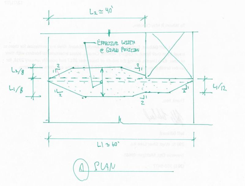
Effective flange width is a shear flow and shear lag phenomenon and as such, it is dependent upon beam length (span length) for its full (progressing) development. Thus, the longer beam can provide for more flange development, but this is somewhat self limiting too, and does not go on (linearly or otherwise) forever as the beam lengthens. The flg. (slab) stress is generally bell shaped with its max. over the beam and decreasing as you move further away from the beam, to some truncated value, as a function of the max. flg. stress you will allow. The flg. stress you use for design is some average of this bell curve, for simplicity of design. Furthermore, the phenomenon is highly dependant upon sudden changes in loads, concentrated loads and reactions (shear changes), and geometric changes. We can probably all grasp the basic problem, a uniformly loaded simple span beam, with the effective flange width growing from some small width at the reactions (beam ends) to some max. effective/practical width at midspan. But, any changes in loading or beam geometry really mess up that simplistic example problem. I don’t have the last few latest eds. of the ACI code so I don’t know exactly what those sections or the commentary say about the issue. But, I suspect it is somewhat empirical and conservative; the 1/4 (15', 7.5' each side for the ‘T’ bm.) and 1/12 (5' on one side for the ‘L’ bm.) values have been around for a long time. Like Rapt, I think I would use the full span length for both, since the phenomenon starts, and grows from the beam ends, but realize, that at the 41' location, and a number of feet on either side of it, you will have an indeterminate stress picture in terms of how the two effective widths (actual slab stresses) blend together. Rapt has probably studied this problem in some detail, I haven’t. I would also add some rebars, in the slab, at the reentrant slab corner. With the computer power and software you have now, I suspect you don’t really need this ‘effective width’ design simplification any longer to have a far better stress picture than we ever had, with a hand held calculator.
 
Creative Engineer,

If you look at the FIB Model Code or Eurocode, they base the flange width on the distance between the points of contra-flexure. So the negative moment zone flange width is much smaller than the positive moment zone flange width in a normal member.

And a simply supported member will have a wider effective flange than a continuous one.

ACI rules on this are very basic, and as you can see from the ACI commentary on this, completely unexplained!

RE dhengr's comment on basing it on FEM modelling, yes, but you would have to decide on what basis you are going to determine it as it is meant to represent a width over which the average stress can be assumed to be a reasonable representation of the stress condition. And most designers these days use the built-in design functions which use the basic code version. And for PT they ignore it completely because some idiots who wrote that section in ACI said you could.
 
dhengr,
Thank you for the elaborate explanation. I am using the effective flange width to model beams in SAP2000 in order for the software to consider the actual stiffness of the beam. I agree that we can take advantage of the full span to calculate effective width in case L/4 or w+L/12 govern after having understood the stress distribution in the beam along its span.
 
Without resorting to FEM etc, I believe this to be the most suitable interpretation of the ACI effective with provisions. Without justification via FEM or testing, I would deem [FULL SPAN / 4] to be somewhat unconservative. In practice, I'd probably take further simplifications in the interest of saving design effort.

c03_nrahhc.jpg


I like to debate structural engineering theory -- a lot. If I challenge you on something, know that I'm doing so because I respect your opinion enough to either change it or adopt it.
 
Status
Not open for further replies.

Part and Inventory Search

Sponsor

Back
Top