I'm making an electric recumbent tricycle. The first speed reduction from the motor will use spur gears. The gearbox is limited in size. I'm using a 23 tooth pinion and 110 tooth gear. Module 1. The pinion will reach up to 13k rpm at top speed, meaning a pitch line velocity of over 15m/s. This combined with the small diameter pinion means that simple splash lubrication isn't enough, and I need to design the housing in a specific way to keep oil in the mesh.
I struggled to find any helpful info online. When I reached a dead end, I decided to make my own data by testing different housing designs. When I first started testing, my biggest concern was how much power I would lose to churning oil. Efficiency is a key goal in this project. I was worried that my initial design with very tight axial and radial clearance between the gears and the housing would sap too much power.
When I got my first test together I found that power loss was not the biggest concern. My initial design did nothing to keep the oil where it needed to be, and at high speeds, I could clearly hear that the gear mesh was running dry.
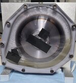
After six iterations, I have some designs that work. But I think it would be stupid of me to finalize anything without seeking advice from competent people.
Here are my findings and my questions.
I started with high radial and axial clearances(1/2" & 1/8") with the intention of bringing them down until things worked the way I want. I then got to the minimum I was comfortable with(.03" & .04") and though it got better, I was having the same issues at high speeds. Increasing the oil level helped across all the tests, but it limited the top speed because my setup was power limited.
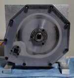
For my fourth test, I had to change something else. I had seen images in research papers of gearbox tests that utilized baffles/oil guides and a false floor between the gears and sump. My initial design was so compact that it didnt have a sump. The first time I implemented these changes, the difference was dramatic. My assumption is that the sump and false floor allowed more oil to be present without increasing the fill line and therefore drag.
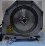
Immediately following this test, I tested another design featuring slight changes based on the research papers' images. I changed the housing to fill the area where oil exits the mesh and empty the area where oil entered the mesh. The effect was that it seems to concentrate the oil in the area leading into the mesh, which led to the best lubrication and least churning losses so far.
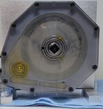
I believe this last change was most important of them all, and applying it to my first design with no sump and no false floor, I was able to get similar performance, though the oil level was more critical than with a sump. Filling slightly too low would lead to insufficient lubrication at high speeds, and slightly too high would bog it down.
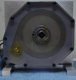
I want to know if there are any glaring changes I should make to my design. I would very much appreciate if someone could point me to examples of gearboxes like this, because I can't find anything.
I also want to ask:
• I tested with 75w90 and 5w-20, but now that I have some power and temperature data, I've realized that I need ISO VG 32 gear oil. I expect the gearbox to operate at around 50-60°c. Does this sound right?
• I need stronger gears, but I can't increase pitch or tooth count. I plan to buy two high quality pinions with a 8mm face width, and sandwich them together to make a 16mm wide gear. I'll do the same with the larger gear. I have access to a machine shop and expect to be able to line up the teeth very well. Any issues you see with this? Any tips?
• I plan to put a max of 21kw through these gears. From the tooth strength and surface pitting calculations, a 16mm face width should give me a good safety factor. Does this sound right?
I struggled to find any helpful info online. When I reached a dead end, I decided to make my own data by testing different housing designs. When I first started testing, my biggest concern was how much power I would lose to churning oil. Efficiency is a key goal in this project. I was worried that my initial design with very tight axial and radial clearance between the gears and the housing would sap too much power.
When I got my first test together I found that power loss was not the biggest concern. My initial design did nothing to keep the oil where it needed to be, and at high speeds, I could clearly hear that the gear mesh was running dry.

After six iterations, I have some designs that work. But I think it would be stupid of me to finalize anything without seeking advice from competent people.
Here are my findings and my questions.
I started with high radial and axial clearances(1/2" & 1/8") with the intention of bringing them down until things worked the way I want. I then got to the minimum I was comfortable with(.03" & .04") and though it got better, I was having the same issues at high speeds. Increasing the oil level helped across all the tests, but it limited the top speed because my setup was power limited.

For my fourth test, I had to change something else. I had seen images in research papers of gearbox tests that utilized baffles/oil guides and a false floor between the gears and sump. My initial design was so compact that it didnt have a sump. The first time I implemented these changes, the difference was dramatic. My assumption is that the sump and false floor allowed more oil to be present without increasing the fill line and therefore drag.

Immediately following this test, I tested another design featuring slight changes based on the research papers' images. I changed the housing to fill the area where oil exits the mesh and empty the area where oil entered the mesh. The effect was that it seems to concentrate the oil in the area leading into the mesh, which led to the best lubrication and least churning losses so far.

I believe this last change was most important of them all, and applying it to my first design with no sump and no false floor, I was able to get similar performance, though the oil level was more critical than with a sump. Filling slightly too low would lead to insufficient lubrication at high speeds, and slightly too high would bog it down.

I want to know if there are any glaring changes I should make to my design. I would very much appreciate if someone could point me to examples of gearboxes like this, because I can't find anything.
I also want to ask:
• I tested with 75w90 and 5w-20, but now that I have some power and temperature data, I've realized that I need ISO VG 32 gear oil. I expect the gearbox to operate at around 50-60°c. Does this sound right?
• I need stronger gears, but I can't increase pitch or tooth count. I plan to buy two high quality pinions with a 8mm face width, and sandwich them together to make a 16mm wide gear. I'll do the same with the larger gear. I have access to a machine shop and expect to be able to line up the teeth very well. Any issues you see with this? Any tips?
• I plan to put a max of 21kw through these gears. From the tooth strength and surface pitting calculations, a 16mm face width should give me a good safety factor. Does this sound right?
