Continue to Site

Eng-Tips is the largest engineering community on the Internet

Intelligent Work Forums for Engineering Professionals

  • Congratulations 3DDave on being selected by the Eng-Tips community for having the most helpful posts in the forums last week. Way to Go!

Help Designing Masonry Wall under Vertical load and Horizontal Point loads

Scotty Boy

Structural
Mar 11, 2025
21
Hi,

I am attempting the design the following masonry wall:
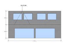
Screen shot wall.png
The wall is under two point loads. One is vertical as you can see in the diagram that has a magnitude of 33.27 kN. There is also another point load and it is horizontal and going into the page at the same location as the vertical point load. This has a magnitude of 30.74 kN. The forces are the result of a roof truss that has a pinned support. Hence, there is a vertical and horizontal reaction on the wall.

I am okay with designing the wall for the vertical load, but I don't know much about masonry under horizontal loads, especially point loads. So, I am wondering if someone could give me some direction on how I design the wall due to the horizontal point load at the top?

Many thanks!
 
Replies continue below

Recommended for you

1) I don't think your load will begin spreading out until it gets below the upper windows,

2) You may be thinking about this wrong. It is unusual for a truss to be putting an out-of-plane load on a wall. It is usually the other way around. i.e. the truss is bracing the wall.
 
1) I don't think your load will begin spreading out until it gets below the upper windows,

2) You may be thinking about this wrong. It is unusual for a truss to be putting an out-of-plane load on a wall. It is usually the other way around. i.e. the truss is bracing the wall.
To piggyback off of this, trusses are typically assumed to be pinned-roller for their supports (I know the Canadian Steel Code says as much, I'd imagine wood would be the same). So you don't have horizontal loads due to the truss itself, but can transmit loads axially through the bottom chord (or whatever chord is bearing on the wall). So unless you are loading this specific truss axially with equipment for example, you probably don't have a lateral load.
 
Is there a structural diaphragm on top of the truss?? If so that should carry the horizontal load to the main lateral force resisting system.
 
I don't think your load will begin spreading out until it gets below the upper windows,

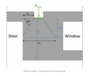
I found this method yesterday here: https://www.structuralbasics.com/masonry-point-load/

Screenshot 2025-05-28 151358.png
The guys says to take the loaded area of half the wall height. I wasn't sure if he meant for one storey on for the entire wall. I did the entire wall.

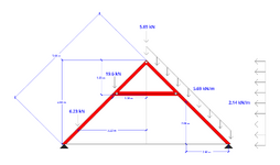
This is what my truss looks like:

Screen shot truss.png
The reason I have pinned-pinned the truss is because it greatly reduces the internal forces. The truss is made of timber.

If there is no lateral load on the wall then that's great news.
 
I found this method yesterday here: https://www.structuralbasics.com/masonry-point-load/

View attachment 10069
The guys says to take the loaded area of half the wall height. I wasn't sure if he meant for one storey on for the entire wall. I did the entire wall.

This is what my truss looks like:

View attachment 10068
The reason I have pinned-pinned the truss is because it greatly reduces the internal forces. The truss is made of timber.

If there is no lateral load on the wall then that's great news.
Unlikely you will ever get that to work out (the truss that is)
Also, I would not even worry about your load spreading out. Just size the big header for the point load. You are pretty close to the end of the wall so arching action may be questionable.
Do you have a mentor of any sort you can run these ideas by?
 
Trusses are typically assumed to be a pin and a roller. A double pin condition essentially eliminates the truss action as all of the horizontal force is resolved into the reaction. You should revise the truss design.
Thank you for your advice, but what do you think about the internal forces being greatly increased? For example, the max bending moment is 70.23 kNm at the collar tie connection for a pin and a roller, but for a pin-pin it is 6.69 kNm.
 
Unlikely you will ever get that to work out (the truss that is)
Also, I would not even worry about your load spreading out. Just size the big header for the point load. You are pretty close to the end of the wall so arching action may be questionable.
Do you have a mentor of any sort you can run these ideas by?
Can I ask what you mean by not working out?

What also is a big header?

No, I don't. This is just a hypothetical project to keep me busy and to extend from what I learned at University.
 
Thank you for your advice, but what do you think about the internal forces being greatly increased? For example, the max bending moment is 70.23 kNm at the collar tie connection for a pin and a roller, but for a pin-pin it is 6.69 kNm.
As you will find, there is no free lunch
 
Thank you for your advice, but what do you think about the internal forces being greatly increased? For example, the max bending moment is 70.23 kNm at the collar tie connection for a pin and a roller, but for a pin-pin it is 6.69 kNm.
I think the truss is not effective since the bottom chord is too high. Typically, the bottom chord is not effective above the 1/3 the height of the truss.
 
Is that a truss? If there is no lower chord, it is hard to model that as a truss, it is just a triangle without a bottom chord. What you have drawn will put thrust on the wall unless you put a big ridge beam at the peak. Even then, it will put some thrust on the wall due to beam sag of the ridge.
 
Last edited:
i agree with XR250, that load will most likely not spread until it gets below the upper windows. No mechanism assuming your drawing is to scale.
 
Thank you for your advice, but what do you think about the internal forces being greatly increased? For example, the max bending moment is 70.23 kNm at the collar tie connection for a pin and a roller, but for a pin-pin it is 6.69 kNm.
Q: If you call a tail (pinned-roller) a leg (pinned-pinned), how many legs does a dog have?
A: 4. Just because you call a tail a leg doesn't make it a leg.
A more accurate model, albeit quite rigorous, would be to use horizontal springs replacing the pinned connections. You would determine the spring stiffness from the supporting structure. Alternatively, you should design the "truss" as a pinned-roller structure and resize the members such that the horizontal deflection is negligible. This is why collar ties placed near the apex don't work very well.
 
the collar tie connection for a pin and a roller, but for a pin-pin it is 6.69 kNm.
As a matter of terminology, a collar tie (aka wind brace) is placed in the upper third of a conventionally framed roof to hold the rafters together at the ridge under high winds and is not part of the gravity load structural system. The joist or bottom chord is when it is near the bottom of the truss. It can be elevated some above the bottom but not the amount you are showing.

Even if you are designing the upper horizontal to be part of your system, it is not a collar tie in framing terminology
 
Okay, guys, can I ask then, what is the best solution for me to design my roof?

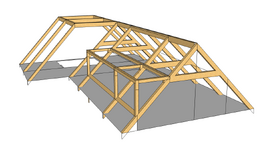
Here is the roof:

Screenshot 2025-05-28 184913.png


Edit: by the way this is a loft space where I want to put a bedroom. Hence, why the horizontal member is at the height it's at.
 
Last edited:
Is that a truss? If there is no lower chord, it is hard to model that as a truss, it is just a triangle without a bottom chord. What you have drawn will put thrust on the wall unless you put a big ridge beam at the peak. Even then, it will put some thrust on the wall due to beam sag of the ridge.
Yes, I don't think it is. My apologies for calling it a truss.
 
As a matter of terminology, a collar tie (aka wind brace) is placed in the upper third of a conventionally framed roof to hold the rafters together at the ridge under high winds and is not part of the gravity load structural system. The joist or bottom chord is when it is near the bottom of the truss. It can be elevated some above the bottom but not the amount you are showing.

Even if you are designing the upper horizontal to be part of your system, it is not a collar tie in framing terminology
Okay. Its just in one of my books called "Design of Structural Timber to Eurocode 5" they have an example of a triangulated roof with a collar tie that is under vertical loading only.
 
What a confusing thread this is! It is impossible to understand the geometry of the structure, let alone some of the OP's comments. Where is the 5.6m high masonry wall on the final post? The flat roof part at the rear of the structure appears to be unstable.

My advice is to seek help from a senior engineer within your firm.
 

Part and Inventory Search

Sponsor