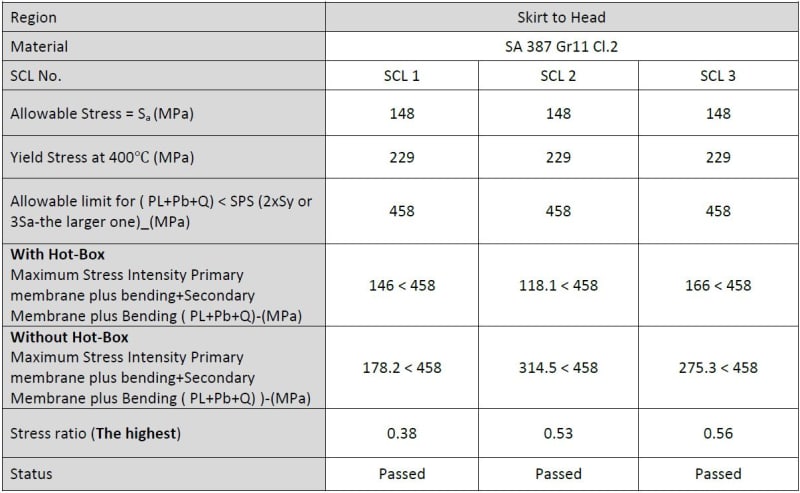
We modeled the vessel without slots and the high temperature in some load combinations caused a very high level of secondary stress and the criteria were not met.
Typically in the skirt you will have high secondary bending stress but low primary stress. IMO for ratcheting to be likely, you need to have a reasonable sustained primary stress in combination with your cyclic thermal stresses. Therefore, if you can't ratchet, it will either shake down to elastic fatigue or result in cyclic plasticity, both of which can be addressed. In the absence of high stresses without thermal, your secondary stress can be reasonably high, if the appropriate analysis is performed. Were you running refractory failure cases that caused the exceedance?
After that, we modeled a hot-box for the vessel and the secondary stresses were significantly decreased.
The HB can be used in conjunction with slots. Out of interest, how did you model the HB? What certainty do you have of the actual efficiency relative to the analysis performed?
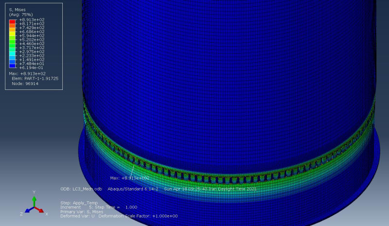
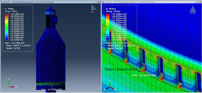
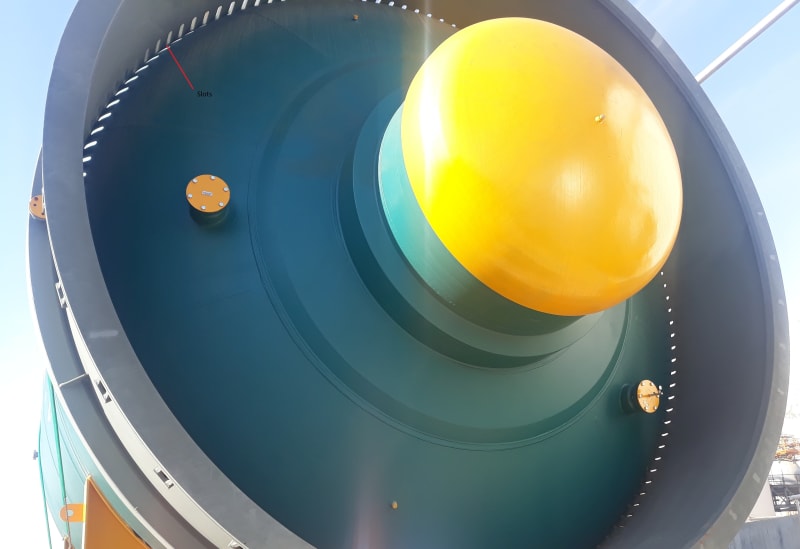
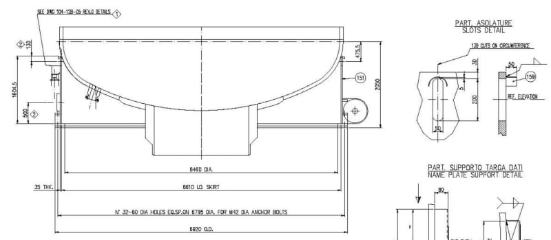
The owner gave us a new plan in which there were 130 slots near the skirt-to-head junction. We assumed these slots are definitely meant for reducing the stresses and removed the hot-box configuration. If the slots were remote from the skirt-to-head junction, I believe they wouldn't be functional.
That is what the slots are intended for. The design isn't actually as simple as just adding slots near the skirt junction. There are lots of factors that influence the design, and there has been significant research in the area. As I mentioned, you should search for some of the publications on this topic. I wasn't saying you need to remove the slots, only presenting another option to consider since you had the ability to redesign the vessel. If it is what the client wants then go with it. However, the 'advantage' of using slots in high cyclic thermal applications is offset by the introduction of fatigue initiation locations. Aside from the design perspective of the slot location relative to the head, which is another discussion, the distance for crack propagation is decrease if you have the slots right at the head junction.
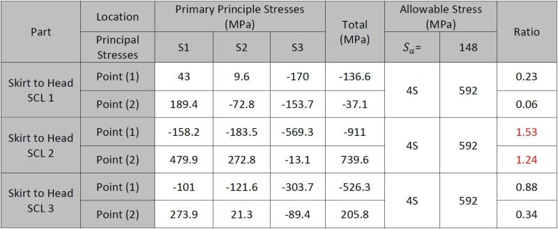
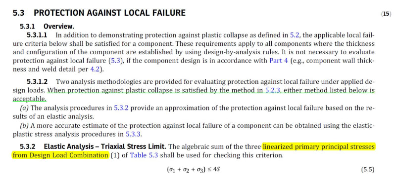
The local failure assessment is actually the trivial assessment for this design. To answer your question, you are allowed to use elastic analysis, what specifically gives you reason to question it? Maybe if you refer to the EP load combination for the local failure criteria in Table 5.5 it might clear this up. Were the stresses in the table you posted actually 'primary' principal stresses?