Eng-Tips is the largest forum for Engineering Professionals on the Internet.

Members share and learn making Eng-Tips Forums the best source of engineering information on the Internet!

  • Congratulations JStephen on being selected by the Eng-Tips community for having the most helpful posts in the forums last week. Way to Go!

Head Loss Due to Pipe Exit Against a Flat Plate 1

Status
Not open for further replies.

nron25

Mechanical
Joined
Aug 3, 2015
Messages
2
Location
US
I am currently working through a problem that I am not sure I can answer without trial and error. The problem:

A tank nozzle has a 90 degree bend on the inside of a tank. Flow is coming into the tank, through the nozzle and bend. The bend is ~3 inches from the tank floor. I am trying to find the associated pressure drop due to the close proximity of the bend discharge and tank floor. Additionally, since the exact distance from the tank floor to the exit of the bend is unknown, I would like to put together a chart showing pressure drop vs distance from floor.

I was thinking that I could calculate a CV factor, but I can only do that if I know the pressure drop. Any thoughts on this? Thanks
 
This geometry sounds very similar to the internal workings of a globe valve, albeit with a very large body. I'd look into globe valve Cv versus position for a valve of the same diameter as your pipe. Finding the Cv versus position may be a problem. Cla-Val has some proprietary values available for sale for their valves.
 
What size is this incoming line nozzle?

Sometimes its possible to do all the right things and still get bad results
 
I think it's more to do with the amount of acceleration between any two points. Draw the flow net.
Head loss is responsible for the acceleration of the fluid from zero inside the tank to whatever velocity you reach in the vena contracta within the nozzle area.
 
For typical inlet conditions, the energy density associated with the pressure will be dominant on the input side.

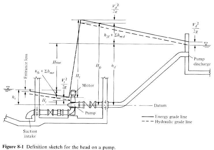
Use the Bernoulli equation to determine the energy based on velocity. The "stagnation pressure" is equal in the tank and pipe. Stagnation pressure is defined to be what you would get if you took the pressure and kinetic terms in the Bernoulli formula and calculated the pressure that would give the same total value all by itself (i.e., if velocity were zero). This is higher than the fluid's actual pressure, due to the effect of fluid velocity entering into the tank and coming to a stop.

If you look at the sketch below, the kinetic energy is shown as v2/2g.

M5_Pumps_and_storage_pfldqb.jpg
 
I am thinking of a nozzle discharging against a flat plate from my past dynamics course. In your case the pressure at the outlet of the nozzle would be the fluid height within the tank above the nozzle and the discharge force would be that pressure time the nozzle X-sectional area. The pseudo force on the plate would be the exit velocity of the fluid times its density time its exit velocity out of the nozzle. The pressure drop would the difference between the two forces divided by nozzle cross sectional area plus pressure of liquid height to the bottom of the tank.
I don't know if this will work but give it a try.
 
Thank you for all the input. I have been modeling it up a few different ways based on the discussion here. I currently have a range of pressure drops based on different modeling methods that I can then use to suggest a path forward. Appreciate the help and discussion.

PennPiper - Didn't want to ignore you, the incoming line is 4.5" OD.

 
Status
Not open for further replies.

Part and Inventory Search

Sponsor

Back
Top