Continue to Site

Eng-Tips is the largest engineering community on the Internet

Intelligent Work Forums for Engineering Professionals

  • Congratulations 3DDave on being selected by the Eng-Tips community for having the most helpful posts in the forums last week. Way to Go!

Fuel Gas Coalescer Filters 1

Stressman76

Mechanical
Sep 9, 2015
7
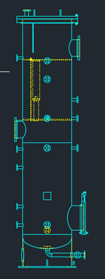
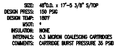
Hi all. At the site I am working at we have a fuel gas coalescer which keeps having filter media burst before the Cartridge Burst Pressure DP is reached. Any ideas or insights on to why this may be happening? The burst pressure dp is significantly higher than what we reach.
 
Replies continue below

Recommended for you

I'll take a stab at it, my background is industrial filtration and cyclonic gas/liquid separation. Double-check your DP gauge/transducer is working properly. If it isn't possible for a brief upset condition such as a water-hammer effect from an initial filling aspect (if this is a possibility, use a slower opening valve), then what about temperature? The differential pressure rating of a filter is an approximation and is based upon a sustained non-pulsating condition found in a laboratory, in the real world fouling and particle/liquid slugs introduce a variable and although temporary, potential for higher DP. It could be a combination of DP + temperature. Some questions I'd ask is "is this a new problem or has it always been a problem? If a new problem, did you change vendors or some equipment upstream of the filter? If a new application, I'd be evaluating whether you are suffering from a water-hammer effect: https://fdpp.com/articles/Water-Hammer.html.
 
I'll take a stab at it, my background is industrial filtration and cyclonic gas/liquid separation. Double-check your DP gauge/transducer is working properly. If it isn't possible for a brief upset condition such as a water-hammer effect from an initial filling aspect (if this is a possibility, use a slower opening valve), then what about temperature? The differential pressure rating of a filter is an approximation and is based upon a sustained non-pulsating condition found in a laboratory, in the real world fouling and particle/liquid slugs introduce a variable and although temporary, potential for higher DP. It could be a combination of DP + temperature. Some questions I'd ask is "is this a new problem or has it always been a problem? If a new problem, did you change vendors or some equipment upstream of the filter? If a new application, I'd be evaluating whether you are suffering from a water-hammer effect: https://fdpp.com/articles/Water-Hammer.html.
I was definitely on the same page with you there on the brief pressure upset event, but it looks like we have a trend on the DP gauge in our software showing the entire operating time. Looking at the trend, it doesn't appear it even came close to the prescribed burst pressure. Wouldn't we see this temporary pressure upset in our trending software?
 
you got a pressure time trace of the DP you can share or details of the bags themselves?

How much margin do you have?

"Coalescer" implies some liquid somewhere.

Where does the liquid get removed before filtration?Is the amount of liquid more than the duty of the filter media?

Lots of unknowns here for you to fill in the gaps.
Below is the DP plot of the system. We changed the filters in August of last year and the DP increased until it was around a max of 9. The filters are supposed to have a burst rating of 32 psi, so we were nowhere close to that. I have also attached the filter literature as well. The liquid gets removed and then pumped down once it hits a certain level. From what I have been told we have never even come close to the max flow rate of the vessel.


Screenshot 2025-06-09 130804.png
 

Attachments

  • LGH Literature.pdf
    160.9 KB · Views: 8
Following-up, other aspects such as temperature and pressure/flow spikes may still be applicable, I thought you might be interested in the graph illustrating rate of clogging. Pressure drop increases exponentially, thus it doubles at 50% clogged and doubles again at 75% clogged etc... Therefore if there is a sudden load applied to the filter media it can 4x to 10x the DP extremely quickly. I suggest having a failed cartridge analyzed by Pall; they should be able to hypothesize on the root cause of failure which may help you determine which aspect of your process to review.
 
Have you checked with the field instrumentation engineer whether you have the right impulse tubing line arrangement to the dp cell for measuring DP in dewpoint gas service ?
 
That's quite an extraordinary variance in differential pressure.

After 5 months of that the filter probably fatigued out.

I'm still uncertain as to how this works and where the liquid goes.
 
That's quite an extraordinary variance in differential pressure.

After 5 months of that the filter probably fatigued out.

I'm still uncertain as to how this works and where the liquid goes.
I agree. It doesn't seem like there should be that much variation in DP across the filters, especially after such a short period. Can fatigue cause the filter to fail?

As far as how the system works:

Our fuel source has liquids that sometimes need to be knocked out. This is accomplished by our coalescer. As the liquids accumulate at the bottom of the coalescer, they eventually reach a level where they turn on pumps which then suck the level out and pump it to a slop line. Does that clear things up?
 
cartridges filters are consumable, don't expect them to last.
The only way to monitor their performance is to measure the water drained over the time .Together with the Delta P this is going to tell you when to change the cartridges.
Yes, Low Capex but Heavy Opex. You should have performed pilot test prior to purchase this technology, my view only but based on my experience using cartridges filters in API production to remove impurities.

I've attached other technology .

Pierre
 

Attachments

  • Desiccant to remove Moisture instead of Glycol.pdf
    471 KB · Views: 0
Last edited:
This video was what I was looking for.


Is this what you have?

That looks to me like there are two liquid sumps. A knock out pot at the base and then a liquid pot in the main coalescing section.

Do you have a sectional drawing or P&ID of this?
Do you have the specicif data sheet for these as it says burst pressure etc is customer specific.

a margin of 3 or 4 to the burst pressure for max DP seems to be common, so your 8 psi is pushing the boundaries. IMHO.

Maybe try reducing the height at which it pumps out both pots. The base pot may just be picking up slugs if it gets too full and the top pot adds to the DP.

Does the DP variance respond to liquid load?

These coalescers look fairly thick and have complex fibres so rapid changes in flow velocity or liquid load will induce flexing and lead to fatigue damage.

Also I know this is really stupid, but the flow does go from bottom to top / inside to out through the filters?
Yes, this is exactly what we have. And yep, the flow does go from bottom to top.

You do have me intrigued on the slug idea though. Help me think through that please. What would cause a slug to be formed and travel to the filters?

I have attached the documentation I have on the coalescer below.
 

Attachments

  • Screenshot 2025-06-10 132237.png
    Screenshot 2025-06-10 132237.png
    18.7 KB · Views: 6
  • Screenshot 2025-06-10 132328.png
    Screenshot 2025-06-10 132328.png
    23.1 KB · Views: 6
You should have dedicated upper and lower sumps, each with its own level control and liquid exit to the downstream collection header. Can we see the PID for this ?
 
A slug can form in any section which has a low spot or an overflow from a downstream piece of kit.

in this case it is more about a sudden increase in liquid droplet density causing a shock to the material on a regular basis.

Also if your levels are too high then some of the liquid or maybe even foam can get swept up with the gas.

but as said before you tend to look at a FOS of 3 to 4 for filter coalescers like this so 9 psi is about the point where they could need changing and not being run like that for 4 1/2 months.

You probably though really need to talk this through with Pell as they will have seen many more operational data than you do.
 

Part and Inventory Search

Sponsor