Continue to Site

Eng-Tips is the largest engineering community on the Internet

Intelligent Work Forums for Engineering Professionals

  • Congratulations cowski on being selected by the Eng-Tips community for having the most helpful posts in the forums last week. Way to Go!

Foundation wall above existing sewer 2

Status
Not open for further replies.

GalileoG

Structural
Feb 17, 2007
467
Hi,

I am designing a foundation wall with a strip footing located above an existing sewer. The footing is minimum 6 feet above the existing sewer (not allowed to go any closer).

As I do not want to add any load to the existing sewer, I am thinking about designing the wall to span over the sewer and place void form under the strip footing where it spans over the sewer.

Any advice on how to design this void form? I imagine I have to be careful not to over design it (designing it for more than the fresh weight of concrete) and that I have to somehow detail it to allow water to come in and disintegrate the void form without allowing soil to come in and close the gap and cause a load transfer.

Your thoughts please?
 
Replies continue below

Recommended for you

Could you use EPS?
Using cardboard carten forms is fine initially but as the cardboard deteriorates, the adjacent soil will erode under the grade beam from either side and you then might have some pressure still applied to the sewer below.

Having said that, 6 feet is quite a distance and perhaps the grade beam load would be significantly diminished (spread out) by the time you get down to the sewer depth.

 
To answer the question about designing the void form - don't bother. They're manufactured commercially and it'll be a lot easier for all involved if the GC just buys one "off the shelf." You're right to be concerned about water getting to them - I read a paper a while back about some testing that was done and if not allowed to get wet the cardboard will remain and transfer load to the soil (or back to the concrete in the case of expansive soils).

I'm not sure I'd be worried about it filling in over time (apart from the hole it would leave on the surface since the material has to come from somewhere). What kind of soils are you dealing with? If it's sandy, it may not work. If you've got clay, you have a chance. By the time the cardboard rots out and the erosion happens and fills the void (remember, the cardboard will still be there inhibiting soil movement for a while after it looses its structural integrity), most of the load will probably be on the footing. Unless you have a cyclic load I don't see the soil filling the void getting compacted to the point where a new deflection in the footing would cause an appreciable stress increase in the soil.

As JAE mentioned, though, 6 feet is a long way down. The sewer probably won't see more than about 10% of the applied load at the surface. Is there a geotechnical engineer involved? They should be able to evaluate stresses on the existing utilities based on your loading. If it's a significant concern (100 year old sewer that could be off on the depth shown on old record drawings, for example), it may be worth contacting one just for this purpose there isn't one involved already.
 
ESP EPS will not help the problem. The ESP EPS remains in place and whatever load is on top of the ESP EPS gets transferred to the soil below the ESP EPS. For example, if you place a sheet of ESP EPS on top of a scale and then you stand on the ESP EPS, the scale still sees your weight. The pipe will also see the footing load. Bridge over the pipe with a grade beam, or use some type of piles. I would not use a void.

 
Agree with PEinc - except it is EPS is it not? (Expanded PolyStyrene)?? :)


The linked paper is for design of buried pipe subjects to highway traffic, but may help you to an extent. Link
 
Your void form and corresponding wall span would need to be quite large in order to eliminate building loads from being applied to the sewer. The void form would need to extend quite far on either side of the sewer. The lateral distribution of soil pressures obviously depends on your soil conditions, but it would be significant over that depth.
 
Hey, do some research on the subject of "imperfect trench" by two old long dead engineers in Iowa. Spangler and (forgot name). This trench was invented by them to allow placing higher earth loads on a fill with a pipe only suitable for low loading. What it is is the zone above the pipe has old fill removed and it is substituted by leaves or straw. The soil on ether side of the trench loose covering then takes over the loading of the added fill above.

When I was the chief soil engineer for Wisconsin DOT back about 1960 there was a sanitary sewer discharge from the Eau Claire city sewage plant going under a roadway. That pipe could not be shut down for any replacement,. Fill to be added above it for the new Interstate was maybe 20 more feet (not exactly sure of this number) so the Imperfect Trench was used and my bet is that discharge pipe still is in use today.
 
There's also elastic EPS available, which we've used as a compressible inclusion to limit passive soil pressures due to structures moving against soil. We used it in a horizontal application, but it might work in a vertical application, as well. As of the last time I looked, Terraflex was the only product of this type still available.

I also found this paper on the use of standard EPS geofoam for protection of buried pipes.

Rod Smith, P.E., The artist formerly known as HotRod10
 
PEinc said:
ESP EPS will not help the problem. The ESP EPS remains in place and whatever load is on top of the ESP EPS gets transferred to the soil below the ESP EPS. For example, if you place a sheet of ESP EPS on top of a scale and then you stand on the ESP EPS, the scale still sees your weight. The pipe will also see the footing load. Bridge over the pipe with a grade beam, or use some type of piles. I would not use a void.

I respectfully disagree. It's simply a matter of the material's modulus and hence its stiffness. Some load might be transferred to the soil directly below, but given the relative stiffness between concrete and EPS, the majority of it would bridge the gap and be transferred to the surrounding soil. If I'm wrong, then a lot of concrete structures in my city are ticking time bombs.

IMO, the best thing the OP could do would be to bring the wall elevation down close to the sewer level, step the footing down right adjacent to the sewer so the bottom of footing is below the invert of the pipe, make the footing discontinuous at the pipe, and then place a thick layer of EPS/XPS foam below the stem of the wall (where you have no footing). Then you ensure that the load from the wall is transferred to the soil below the pipe.
 
STrctPono - wouldn't it be more appropriate to compare the modulus of the EPS to the modulus of the soil rather than the concrete? The footing will have a more-or-less uniform stiffness along its length, but the elastic foundation that supports it will be variable. If the soil is significantly stiffer than the foam, then the foam will compress a little (transferring some load), and then the stiffer soil will take up the slack as the footing spans over it. This goes along with oldestguy's "imperfect trench." We'd just be updating it to use soft foam rather than loose, uncontrolled fill. Maybe I'm misunderstanding your meaning, though.

 
I think the benefit of replacing soil with EPS is the reduced overburden. That way adding a surcharge load can be offset by the reduction in overburden. But on the other hand you lose the beneficial arching/load-spread action of soil. With EPS fill over the pipe, the footing load would transmit directly to the pipe without much attenuation. It's lightweight but doesn't create a "void", in a structural sense.

I've never used void forms so I can't speak to that. But PEInc's suggestion of a grade beam with piles to span over the pipe makes sense.
 
bones206, your conclusion seems to be based on the assumption that the foam has a stiffness at least equal to that of the adjacent foundation soil. I believe that standard EPS is actually less stiff than typical granular soils. I know that is the case for the elasticized geofoam material I referenced above.

Rod Smith, P.E., The artist formerly known as HotRod10
 
Fair point. I didn't think the difference in stiffness was large enough to mobilize soil arching around the foam, but maybe some low density foams with lower stiffness could perform well. I don't know if you could claim that additional loading would be entirely avoided though. I would expect some proportion of the load to transmit through the foam.
 
phamENG - my interpretation of the OP's proposal was as attached. I've also attached what I suggested as a better solution. Someone (I'm assuming the Sanitation Department) imposed a restriction on him to not go any closer than 6ft to the sewer line so I guess there's no arguing that point. Either way, my assumption that the concrete's stiffness is variable based only on the distance that it has to span over the EPS. I would assume that the soil adjacent to the pipe would have a more or less uniform subgrade modulus (not variable). The area that he would be looking to span with his EPS is probably backfill material anyway. I look at the problem as if the concrete footing is a beam spanning from one side of the EPS to the other. The EPS may not be a pure void but rather a distribution of soft springs on the bottom side of the beam. The springs have an equivalent stiffness related to the EPS material's compresssive modulus. The longer the span of the beam the more load goes into the softer EPS. Again, not zero load but greatly reduced load to the pipe. I don't think this is the best solution but I think there is some validity to the OP's proposal.

PEInc's suggestion of a grade beam with piles would be the best solution but sometimes bringing in a pile driving operation for 2 piles might not be the most cost effective solution. Not sure the size of project or scope of work.
 
 https://files.engineering.com/getfile.aspx?folder=a7c7fb25-caa9-4f09-921f-36257400c842&file=SKM_C454e20011607400.pdf
Maybe you're on a fool's errand to transfer NO load to the pipe. Assuming a 2' wide strip footing at 6' over the pipe, an elastic analysis (Boussinesq) says the stress increase is 0.20 x footing pressure. At say 3000 PSF footing pressure, this is 600 PSF, about equivalent to 52.5' of added soil load. If you have an effective 4' wide gap in footing over the pipe, the stress influence is still 0.11 over the pipe, or 330 PSF for a 3000PSF. So this void form is a lot of effort for reducing the load on the pipe by 270 PSF, which is likely insignificant for the pipe.
 
Found a good paper with in-situ test results:


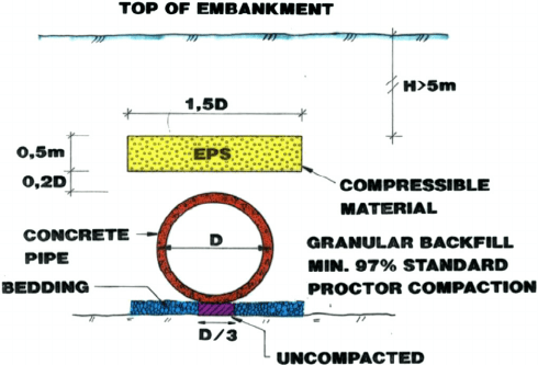
The NPRA has instrumented 4 locations and monitored the reduction in vertical stress (Vaslestad et al., 2011). These studies show that the long-term measured vertical pressure above the crown of the pipe ranged from 23 to 25% of the overburden pressure for installations with granular backfill material, and about 45% for installations with cohesive soil backfill. It was found that the performance of the induced arch was largely affected by the type of soil used in the embankment construction. Field installations with granular fill reduced the vertical pressure over the culvert more than those with silty-clay embankment. Nonetheless, the measured earth pressure for the section of culvert without the induced trench installation showed pressure that was 124% of the calculated overburden pressure. The final compression of the EPS geofoam block at the end of embankment construction ranged from 27% to 32% for concrete pipes with granular fill, and 50% for cast-in-situ box culvert with cohesive fill.

Edit: This was the setup for the above results. A geofoam version of the Imperfect Trench.

Imperfect-trench-method-with-EPS-geofoam-compressible-inclusion-placed-atop-concrete_vecbga.png
 
STrctPono - I think I got it. You're comparing foam stiffness to concrete to determine load sharing characteristics through deflection compatibility. I think we're looking at it from slightly different perspectives but arriving at a comparable conclusion.

The point is probably moot by now, though. OP has been gone for 3 days - this doesn't sound like the kind of job with a budget to work on it for that long so (s)he probably took what they needed and moved on...
 
I didn't think the difference in stiffness was large enough to mobilize soil arching around the foam, but maybe some low density foams with lower stiffness could perform well. I don't know if you could claim that additional loading would be entirely avoided though. I would expect some proportion of the load to transmit through the foam.

The pressure on the pipe wouldn't be completely avoided, but it would be lower and more predictable. The pipe has to be able to resist some soil pressure. Generally, pipes can handle significant pressure if it's uniform. The trick is to limit the pressure from the footing to a value similar to the pressure on the soil for the remainder of the pipe, so that there's not differential settlement of the soil causing excessive shear on the pipe.

What qualifies as excessive shear varies widely depending on the size and type of pipe. If the OP would post that information, the responses would likely be much more relevant.

Rod Smith, P.E., The artist formerly known as HotRod10
 
Status
Not open for further replies.

Part and Inventory Search

Sponsor