Continue to Site

Eng-Tips is the largest engineering community on the Internet

Intelligent Work Forums for Engineering Professionals

  • Congratulations cowski on being selected by the Eng-Tips community for having the most helpful posts in the forums last week. Way to Go!

Flow in 4" cast iron pipe 2

Status
Not open for further replies.

PEDARRIN2

Mechanical
Oct 1, 2003
1,287
I am trying to calculate the force on a fitting in an 4" interior horizontal storm pipe (cast iron no hub with no hub bands)

But first I need to determine what the actual flow is.

assumptions/knowns:

piping is full (single phase, no air bubbles)
d = 3.94 in
L = 20 ft (10 vertical and 10 horizontal)
Single 90 degree elbow which I was using K = 30 f(t) which the f(t) is 0.17 per Crane. This gives me an L/D = 26. I know I am mixing methods/equations, but there is no data I know of relating the friction factor of a cast iron 90 to equivalent length L/D - so I use Crane's K factor section.
friction factor: 0.041 based on iteration of Colebrook formula
Velocity at top = 0
Pressure at both top and bottom are 14.7 psia (open to atmosphere)

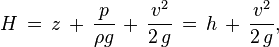
So using Bernoulli's with the h(l) factor included, I get

10 = [V(2)^2]/2g + (1+fL/D)*[V(2)^2]/2g

From this, I get a final velocity of 17.6 ft/s which equates to a gpm of 668.8

Given that my math/assumptions are correct - I do not know if this is realistic.

Comparing to what I would get if I used Manning (knowing there is no static head), I get 87 gpm for a fully flowing pipe at 1/8" slope.

Now I know I am not accounting for slope in the first calculation (which would only add 1.25" to the z factor), but does adding 10 feet of static really increase the flow by approximately 8 times?

Any help would be appreciated.
 
Replies continue below

Recommended for you

Yes, it would. If you have 10 feet of headloss across 20 feet of pipe, you should expect a flow of approximately 700 gpm.

However, in your case, this is also an unrealistic scenario.

The flow is not entering the pipe at the top at 17.6 ft/sec velocity. It is gravity flow. It takes 8 seconds to reach 90% of terminal velocity. The flow would also have to be full pipe. Partial flow in a vertical pipe would have a terminal velocity.

The pressure at the bottom can not be more than the static head of 10 feet or 4.3 psi. The maximum force on the fitting is 4.3* 3.14*2*2 = 54 lbs.
 
bimr,

Thanks for the response.

I only gave a partial part of what I am trying to calculate.

I eventually want to calculate the momentum force on a downstream fitting, say at the end of my 10 feet of piping. So I will have both a pressure component F=PA and a momentum component.

With no hub pipe, there is a requirement to restrain horizontal piping at the fitting, generally 5 inches and greater. Generally it is two riser clamps and some all thread rod. One manufacturer makes a "engineered" part ( The couplings used are shown ( The standard for the couplings are shown, (
The current guidance is the fittings must be restrained with a 10' head placed on them, which is what the plumbing system is hydrotested. If a static head was all that we would be concerned about, I would not have an issue. It is the freak storms that occur once in a while which causes surges in the piping. If I have 10' of water in a riser for a short period of time (enough to fill both the vertical and the horizontal pipe), the horizontal piping would not (I am assuming) not follow Mannings, but a pressurized system which would use Darcy/Bernoulli.

If I have approximately 700 gpm of full pipe flow, if even for a short period of time, the flow could exert enough force to blow out the fitting.

If the flow calculation is correct, I want to start a conversation about what forces should be expected and whether the fitting restraint would be able to handle them or whether more restraint is required.
 
The total energy in the pipe system can not be greater than the 10 feet of static head since the pipe is open to the atmosphere at the top of the pipe.

187d6853e6b3183e324fadb92b51735a_fpha3y.png


Assume you have a pipe with 10 feet of head flowing through a 20 feet pipe segment. The 10 feet of headloss (energy) is lost over the 20 feet segment.

The normal restrained joints will easily handle the forces.
 
It appears you are trying to design a siphonic drain system.

These are designed so that the residual pressure at the exit point of every flow path is approximately 1.5 psi. You have 10 feet of available head, design the segment so that you have 6.5 feet of headloss across the segment, leaving you 1.5 psi at the outlet.

Δpavailable = Δha . g . ρ

Δha = available height from roof membrane to exit point
ρ = mass density of water at 10oC: 1000 kg/m3
g = gravitational acceleration: 9,81 (m/s2)

Δploss, ls = l . R + Z

l = pipe length (m) = the length of the pipe section
R = pipe friction pressure loss (Pa/m) = (λ/di) (0,5 . v2 x r)
with:
λ = pipe friction factor according to Pradtl-Colebrook (wall roughness kb = 0,25 mm)
di = pipe section design diameter (m)
v = flow velocity in flow path (m/s) = Qh/di
ρ = mass density of water at 10oC: 1.000 kg/m3
Qh = rainwater load for the total roof section drained by the pipe


The maximum velocity in these systems is approximately 8 ft/sec which is approximately 300 gpm in the 4-Inch ductile iron.

Link to design document:

 
bimr,

Siphonic roof drainage is not what I am looking at. It uses pressure type fittings and no slope.

I am looking at a situation where a normal storm drainage system is surcharged due to a higher than anticipated storm event, i.e. higher intensity, shorter duration.

We typically design for a 100 year, one hour duration storm. For where I am at, that is ~3 in/hr. But occasionally we might see 3 inches of rain fall within 15 minutes. This can, for a short period of time, surcharge the piping.

It is my thinking the piping will eventually fill both the vertical and horizontal sections so I would use the momentum equations to determine the force exerted on a pipe bend by that water.

I do not understand why, if you have 10 feet of static, starting at atmospheric pressure and at zero velocity, and ending with atmospheric pressure, gives you 300 gpm/8 fps of full flow in the pipe, even when calculating friction loss, you would not have to look at the momentum of the water as it travels through the piping. 300 gpm through a 4" pipe would have a constant velocity (Q=V*A) where Q and A are constant. I understand pipe friction will play a part, which is why I was using Bernoulli's equation, not Manning's to determine the flow rate.

If I am incorrect, please let me know.

My momentum calculations indicate, at 300 gpm in a 4" cast iron pipe as it enters a horizontal 90 fitting, I would have 465 lbf acting on the fitting from momentum. Pressure would contribute 267 lbf to the fitting. These would act at a 45 degree angle (or 135 degree) depending on how you look at it.

I do not know if the pipe restraints would be able to account for this thrust. That is the question I want to investigate - but I need to make sure the engineering is correct.
 
What is a "normal storm drainage system"?

Don't see where you are coming up with the force of 465 lbf . Forces on the piping can be determined with the online calculator at the link below. If you enter the typical pressures and velocities, then you see that momentum thrust is a very small percentage of pressure thrust.


Almost all the thrust in almost all water pipelines comes from pressure, not momentum. Momentum is only significant if your pressure is very low and the velocity very high. So whether the water is flowing or not is usually irrelevant. The highest thrust load happens under test pressure when the water is stationary.

The velocity of the fluid (or momentum effect) is normally neglected in the DIPRA suggested thrust calculations, as at normal low water and wastewater fluid velocities the effect is normally relatively insignificant.
 
you may be missing a few things

assuming the water enters the pipe at the top and you have full flow (difficult to achieve with a vertical pipe under gravity flow conditions), you will have an entrance loss. assume a loss coefficient of .5 and your inlet head loss is about 1.5 feet. your bend will cause additional loss, perhaps another .3 feet. the rest of your head will equal the friction loss of the pipe. so you will have about 8.2 feet of headloss due to friction.

assuming your mannings n value is about 0.013 than you could expect about 540 gpm flow rate at a velocity of about 13.8 feet per second.

your maximum pressure is static, 10 feet of head, about 4.3 psi or a total of 54 pounds. Assuming you do not have full flow, I would assume about half that flow rate.
 
Once you determine with some rigor the internal pressure and flow velocity in operation at the bend (as others have mentioned, some less than due to 10 feet of head), I believe the thrust force considering resultant pressure thrust and momentum at a pipeline bend can be approximated with the formula as follows:

T = 2 [ P + (rho)V^2 /(144g)] A Sin (delta/2) in lb
Where,
P = internal pressure at bend (psi)
A = cross-sectional area (for iron pipe normally based on the pipe barrel O.D.) in in^2
delta = bend angle
rho= fluid density in lb/ft^3
V= velocity of fluid in the pipe in ft/sec
g= gravitational constant in ft/sec^2

I think you will find the total force to be resisted at the bend of this small diameter piping is only a fraction of what you somehow calculated before, and even at e.g. 8 fps flow velocity the force due to momentum would not be much.
 
bimr (and all),

I want to thank you all for helping to sharpen my skills on this issue.

A normal storm system is one designed to be self venting, partially full, per codes and designed per Manning.

I am trying to look at a situation where the rain fall event exceeds this design scenario and surcharges portions of the vertical and horizontal piping.

There was a recent study by ASPE which indicates roof drains will allow more flow into the piping than what the plumbing code allows per pipe size especially if there is a buildup of water on the roof. This is a situation that could cause the surcharging I am looking at.

I found the error in my calculations. I forgot to divide by g(c) = 32 in my momentum calculations. I worked an example problem from a text book in SI until I knew my calculation method was correct, then converted the answer to the imperial and found I was off by a factor of 32, which made immediate sense.

So when I fixed this, the results became more in line with what has been indicated.

I am still trying to figure out how the friction loss is being calculated in the above posts. I am not sure, but I may have misrepresented my problem. The upper part of the pipe is open to atmosphere, i.e. at a roof drain and the end of the pipe system is open to atmosphere, as in a catch basin outside the building.

But, I am not sure that equates to the fitting in question is at atmospheric pressure at its downstream side. So, I have not used up all the potential energy from the static height at the downstream side of the fitting.

Please excuse the rough sketch of what I am trying to do.

Roof drain at atmospheric
/
/
/ 10 ft vertical
/
/
/ 10 ft horizontal, full/pressurized
____________________ <---------90 fitting (calculating force on this fitting)
/
/
/
/
/
/ long continuation (hundreds of feet)
/__________~ ~__________________ catch basin at atmospheric

So there will continue to be flow and at some point the flow will resume flow which can be calculated by Manning.

I have been using the h(l) = fL/Dv^2/2g to determine the loss due to friction.

f = 0.022 (iterative approach of the Colebrook equation using a absolute roughness of 0.0004).
L/D = 26, 20 feet of pipe and 6 feet for elbow.
V^2 = 64

From that I get h(l) = 0.572 feet.

So with the 1.5 ft loss for entrance, by the time I get to the 90 under question, I should have approximately 8 ft (3.46 psi) which would mean I have 11.24 psi at the inlet of the fitting.

Does that sound correct?
 
your pipe flow is controlled by gravity. the maximum pressure you could have at the fitting is the static head of 10 feet. so at zero flow and assuming for the moment that your pipe was plugged and completely full of water up to the top, your pressure at the fitting would be 10 feet of water (4.3 psi). you cannot have a pressure greater than that.

If you are going to calculate friction losses, you will need to calculate the flow rate. the flow rate in a gravity system is directly tied to the head at the water source, elevation of the outfall, pipe size and head losses due to entrance, exit, fittings and pipe friction. So you will need to calculate the headloss in your hundreds of feet of pipe in order to estimate the flow and velocity in your drain. yes, you will need to iterate.
 
cvg,

I understand the maximum pressure would be dictated by the static height, so I cannot have any more than 10 ft (4.3 psi), based upon what I have.

I thought I was doing just what you stated. I used Bernoulli with a friction factor from Darcy added. But the friction loss I am calculating seems to be much less than what other posters are stating I should have.

I am trying to figure out what I am doing wrong or where I am misrepresenting the issue, so I am not getting relevant feedback.
 
suggest you start at the downstream end, calculate your losses, plot your hydraulic grade line and energy grade line. compare to the static HGL and evaluate flow into your entrance structure to make sure you do not over estimate your flow rate.
 
Just to make clearer, as I sense some confusion appearing at least in areas in this thread, by "cvg's very good advice that you start at the "downstream" end in your overall headloss determination I think he means wherever beyond that point the water actually exits to open air.
Unless there is some kind of dynamic action, per my understanding of what you have I don't see how you could get any more force (on the ell for whatever reason in question) than that due to any pressure test or 10 feet of elevation head (i.e. ~4.3 psi static pressure or what more pressure is actually applied in the installers proof test).
Also, if there are actually "hundreds" of feet of all closed? small diameter piping beyond that ell, unless the downstream piping has substantial slope I doubt you'll be getting much flow velocity in this line as well (even without "blockage"!)
 
My analysis is not meant to extend for an entire piping network, which, in reality, would likely include many more vertical drops (through floor stories), connection from other pipes from other roof drains, increases in pipe size until it gets to the exterior of the building to connect to the site storm sewer system. In all likelihood, somewhere along the way, the flow will slow down due to downstream friction and return to partially full "Manning" flow for which the drainage system is designed.

There might be some hydraulic jumps that partially (or fully) fills a horizontal pipe just downstream of a vertical drop. this will likely cause some two phase flow and some pressure disturbances as well. To try to "model" this would be beyond what I am trying to do at present - although I would like to try to understand this phenomena and its effect on downstream fittings as well but that is fodder for another post.

But I feel like I am getting conflicting input. Some of the posts indicate I could have flow in the order of 100's of gpm, while others indicate I likely would not have this much flow. If the piping is indeed full, for a short period of time, and assuming that it is not two phase (carrying air along with it), which I know is a big assumption, but I want to look at the simpler one phase flow before I try to look at two phase. Then the only thing that would prevent a flow of 100's of gpm would be the friction. Because, without friction, Bernoulli's indicates ~700 gpm.

So with a friction factor for cast iron pipe of 0.021 (my previous factor of 0.041 was incorrect because I was using a wrong epsilon roughness for the pipe material), I am still getting ~20 ft/s at the end of my 20 feet of pipe and one elbow (before I get to the elbow I am trying to calculate the force).

I have corrected my calculations so the momentum portion is in line with where it should be, but I want to have a good grasp on just what flow I should anticipate.

Again, thanks for all the input.
 
PEDARRIN2,

This is more complicated than piping a 4-Inch pipe from roof to drain.

The reason that you are having the problem is the size of the drain. What you have to do is to reduce the size of the roof drain to minimize the velocity in the 4-Inch pipe. If you were using a 2-Inch roof fitting, the fitting would allow a much smaller flow to pass.

You have a maximum pressure of 4.33 psi (from roof to drain) available. Your outlet pressure should be 1.5 psi. Therefore, you should take 2.88 psi headloss across the roof drain fitting, 2x4 reducer, and the 4-Inch downpipe.

The design for the entrance losses should be high enough to limit the velocity in the 4-Inch pipe to approximately 8 ft/sec or 320 gpm.

If you have a large building, you can use the flow through the horizontal piping to provide the headloss. The problem is that you are only working with a single vertical 4-Inch pipe.

Note that the building roof should have some type of emergency overflow to limit the total rain load on the roof.

 
 http://files.engineering.com/getfile.aspx?folder=b34c34e6-1331-4ed4-b879-7cbc3f849ae0&file=roof.pdf
You cannot disregard the piping beyond the first 20 feet. Even if you want to look at a "worst case" by saying the pressure after 20 ft is atmospheric that may not be true, because if the pipes are running full you could have a siphon established and have pressures below atmospheric in some places. I suspect this is a problem that will require a full-blooded network analysis to get realistic flows.

Katmar Software - AioFlo Pipe Hydraulics

"An undefined problem has an infinite number of solutions"
 
the inlet will definitely limit the amount of flow into the system. Downstream friction and other losses may also restrict the flow rate. Flow will very likely alternate between full and partial flow. first step has to be estimating the flow rate which is an iterative procedure and can only be done by considering both upstream and downstream control points. you cannot make an assumption that it is or is not flowing full. It may be doing both. Ignoring friction losses because you don't know what they are is simply not an option.
 
All,

I think we are still talking apples and oranges. I think I am getting responses to tell me about determining a particular tree, when I am looking a bit more for a small grove.

I don't have an actual, specific building storm piping design that I am trying to analyze - so a full network analysis is outside of what I need to do. I do not even think I have the ability or the tools to take on such a task.

I know this would give the big picture, but I am trying to hone in a bit tighter on one aspect of what could be occurring, full flow in a horizontal pipe and its effect on a fitting.

bimr, reducing the size of the drain would likely help, but I would be limited by what the plumbing code allows. For a certain roof area, I have to use a certain pipe size. The issue is, say a 4" roof drain, allows more water to flow, than the 4" pipe is supposed to be allowed to flow, per code. Thus, the pipes need to get bigger, which the code writers are looking at.

ASPE (American Society of Plumbing Engineers) used a similar set up to determine that roof drains allow more water to flow than the pipes are allowed to flow, as I mentioned above. See the attached.

The building would have some sort of emergency drainage, usually a separate roof drain system where there is a 2"-4" standpipe in the roof drain body.

katmar, yes, I am making a lot of assumptions with this scenario, but for what I am trying to determine (force on a fitting), I think I am ok.

Say, I created a test rig where I had a tank/vessel that had a 4" roof drain in the bottom, with 20 feet of 4" pipe, with two elbows, and the last discharged at to atmosphere into another tank, located below it. This tank had a variable speed pump that discharged water into the first tank. The pump rate was adjusted to maintain the 10' head in the system. With this, I could determine the flow through the pipe and thus assume I could determine the force on the last elbow. Now I realize there would be some force due to the water exiting the elbow, so maybe a short piece of pipe that put that effect further downstream.

I know this would not be exactly the same as if this piping was attached to a network of piping where there would/could be full flow, partial flow, siphonic action, etc. But I would assume, the flow rate derived from the test would be close. Even if the error was 10%-20% - that would get me in the ball park of what I am trying to do. Manning tells me I would have 87 gpm (without head). Bernoulli tells me I would have ~700 gpm with the assumptions I have made. If the actual flow is 600 gpm, that would be satisfactory.

Now I do not have the resources to do this so what I am trying to do is derive this flow from calculations I can do.

cvg, I do not want to ignore friction losses. I am just trying to find a way to fairly accurately calculate what they are within the limits of my analysis.
 
 http://files.engineering.com/getfile.aspx?folder=87254ed6-ba40-4276-a937-25a489393d5d&file=ASPE_Storm_Drain_Flow_Research_Project.pdf
Status
Not open for further replies.

Part and Inventory Search

Sponsor