JoshPlum said:
![[lol]](/data/assets/smilies/lol.gif "[lol] [lol]")
![[tiphat]](/data/assets/smilies/tiphat.gif "[tiphat] [tiphat]")
@drift/Josh
Yea the flexible diaphragm design regions (defined separately from the slab/diaphragm edge geometry) are limited to perfectly rectangular geometry, bounded on all 4 sides by lateral elements. Makes sense from a design level standpoint.
drift said:
Josh, Like I said it was been a little while for me too but My understanding of semi-rigid workflow in risa is to use a mesh of plate elements to represent the floor. They are 'General' material and their stiffness essentially comes from plate shear and bending deformations. The user has to determine appropriate plate material and thickness to get the 'semi-rigid' wood diaphragm. My thought was that I want the displacement of the center of a rect. diap. region to match the hand calculated NDS deflection for the same load. So I would adjust the plate properties to get an 'effective' shear modulus that incorporates those additional deflection terms from the NDS.
That's correct, however...to be completely honest I've simply used the built in material "gen_plywood" and set the thickness to 3/4" or whatever. I've tweaked the material properties (E, G, etc) but haven't noticed significant difference in distribution. Half baked rationale being that the stiffness of this material is ballpark equal to the stiffness of the shearwall material. I believe the plywood material is orthotropic and diaphragm material is isotropic. Walls are orthotropic to account for different vertical stiffness due to wall studs, etc. They explain it in the documentation. You can define the diaphragm material as orthotropic, in the case of metal deck where the two directions have different stiffness properties for example. I haven't experimented with that though.
Another thing is that with flexible and rigid diaphragms, the story force is simply applied to a single node (various nodes for different eccentricity cases. i.e., 5% offsets, etc) and the flexible diaphragm attributes the forces (proportional to area of diaphragm DESIGN REGION to total diaphragm area (i would think that's how it's proportioned?) and applies the calculated forces as horizontal line loads along the lateral elements' length as a separate "transient load" case - 1 case for each direction and wind/seismic. If you don't define the design regions explicitly I THINK the program will try to subdivide the flexible diaphragm between lateral elements....I think.
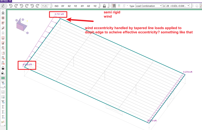
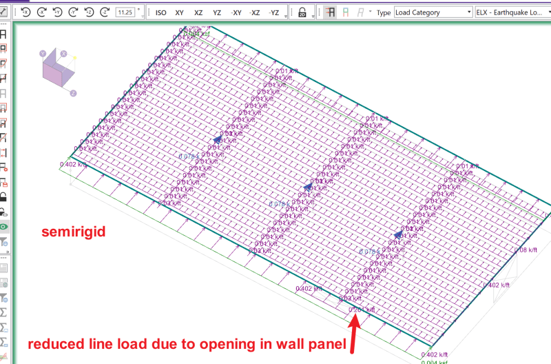
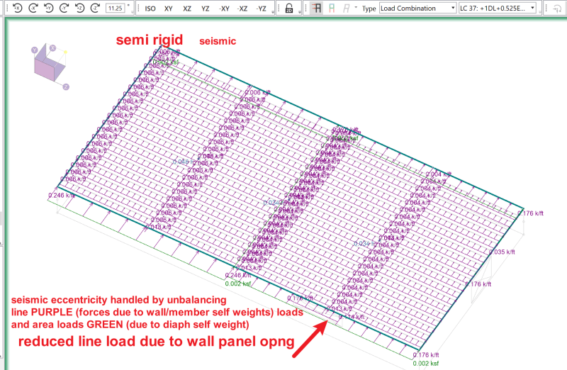
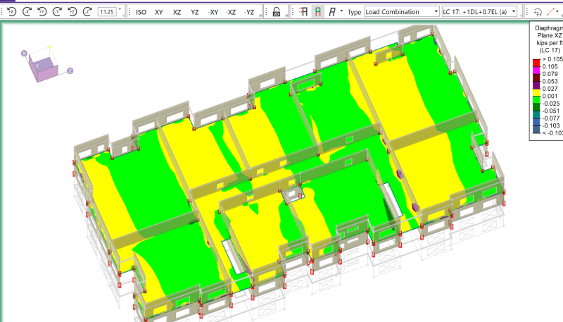
With semi-rigid, the program will generate different load cases altogether. The loads for WIND are simply applied as line loads along the edges of the diaphragm and it does take into account eccentric cases if you so desire, by calculating the projected forces at some angle. For SEISMIC cases, it will calculate: 1) line loads due to member/wall panel self weight * acceleration and 2) a lateral area load applied to the diaphragm (which is then transformed into point loads applied to the semirigid diaph mesh nodes based on tributary mass of the individual plate elements. This is similar to how RAM Structural system applies seismic loads to semirigid diaphs.
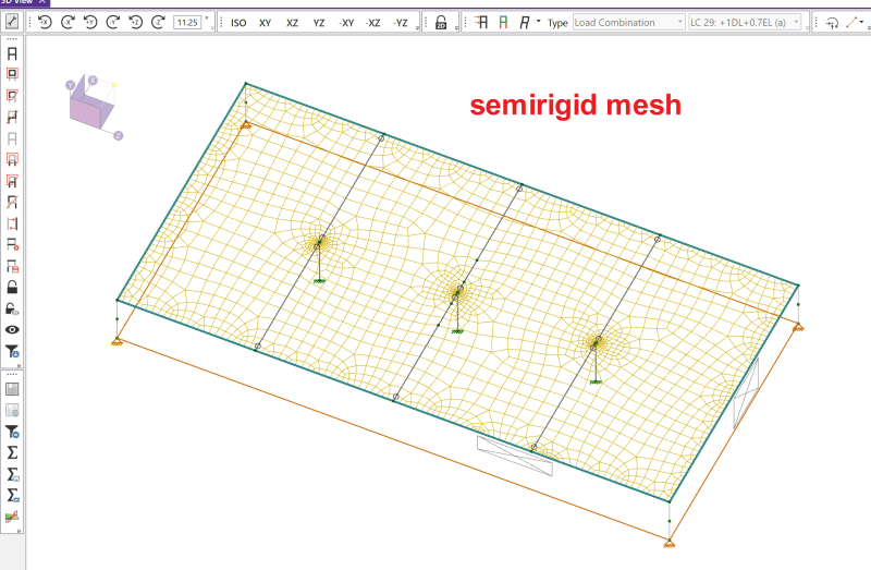
Also, with semirigid, you don't have to define any regions. Just the diaphragm edge. And it doesn't necessarily have to have lateral members around all edges...i'm pretty sure. And you don't have to bother with drawing any plates or anything. Just define the diaphragm perimeter (and openings if there are any) and the program auto-meshes the diaphragm the same way it meshes wall panels. You can define the mesh size also. Bentley (RAM SS) did a sensitivity study regarding mesh size and how that affects load distribution. Their findings showed that meshes finer than ~6ft don't provide that much more accuracy. Rather, the variations in forces delivered to a given frame start to converge quickly at a 6ft mesh. E.g., a 6ft mesh will provide results within 5% or so of a very fine mesh, but has a much faster analysis time.
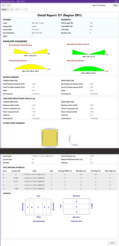
FLEXIBLE STUFF
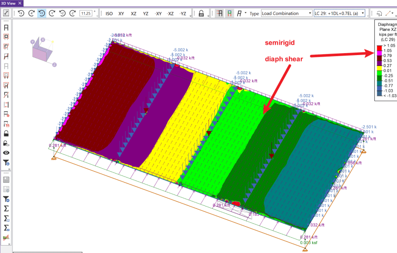
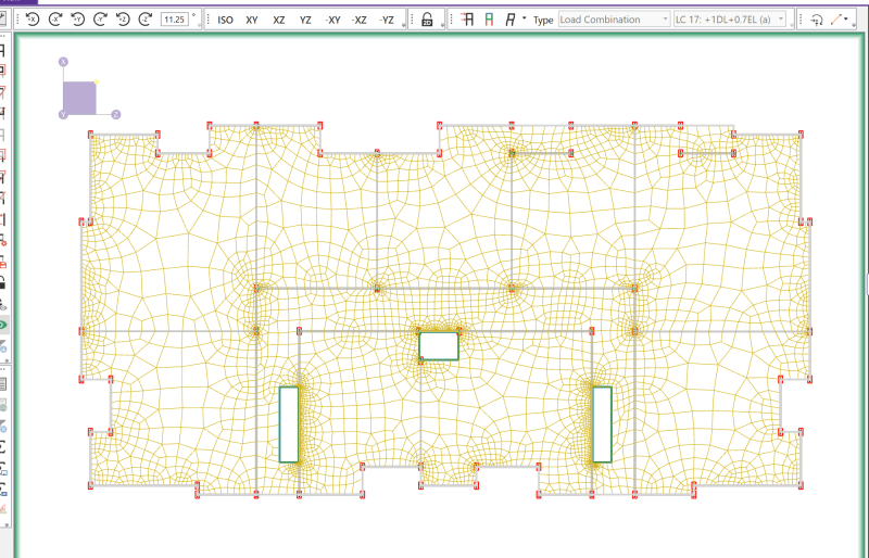
SEMIRIGID STUFF
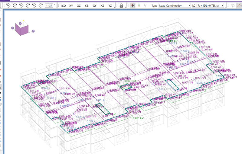
Here's a sample from a project where i used semirigid. This is just one floor plate isolated.
drift said:
My largest complaint about the RISA workflow with flexible diaphragms, is that the diaphragm didn't actually provide continuity and interconnection between the modeled elements. If you model a real structure in 3d then use RISA flexible diaphragms, only the load is attributed to lateral elements based on flexible diaphragm assumption, there is no physical element there. What this ended up doing was creating instabilities for every wall that is anchored to the diaphragm and the model wont even run. Not sure why they even bothered to give us this option given this fact. From what I saw the only way to reasonbly use flexible diaphragms in Risa was to restrain the walls out of plane and analyze one direction at a time. Not really 3d.
Yea that can be a pain in the butt. It can be stabilized with strategic placement of lateral elements to brace the walls, and just keep an eye on any forces that develop in those members. Pretty tedious. That's one of the big reasons I started experimenting with semirigid. Semirigid just meshes it all together.
Well. That took a while
")
Oh, and big shoutout to the risa>revit link! Once you study it for a while and figure out exactly what it is trying to translate you can make a pretty solid workflow. Great for the more complicated apartment type projects with lots of weird gemoetry and wall openings, etc. On the example above I had used the risa>revit link to build that model. I stripped down the architect's revit model to just the bottom floor, cleaned everything up to essentially ensure connectivity between all walls, and make sure all openings were properly modeled (i.e., change all doors to one type and make sure it is cutting the physical wall properly. sometimes it gets confused if there's a curtain wall as opposed to a window/door/or straight opening). Then I think i just exported that single level and then duplicated those levels as children within risa floor. Pretty slick once you get the hang of it.