Continue to Site

Eng-Tips is the largest engineering community on the Internet

Intelligent Work Forums for Engineering Professionals

  • Congratulations waross on being selected by the Eng-Tips community for having the most helpful posts in the forums last week. Way to Go!

Fin Bracket Bending/Tension/Shear

Status
Not open for further replies.

astridmcb

Structural
Nov 4, 2020
4
Hi guys,
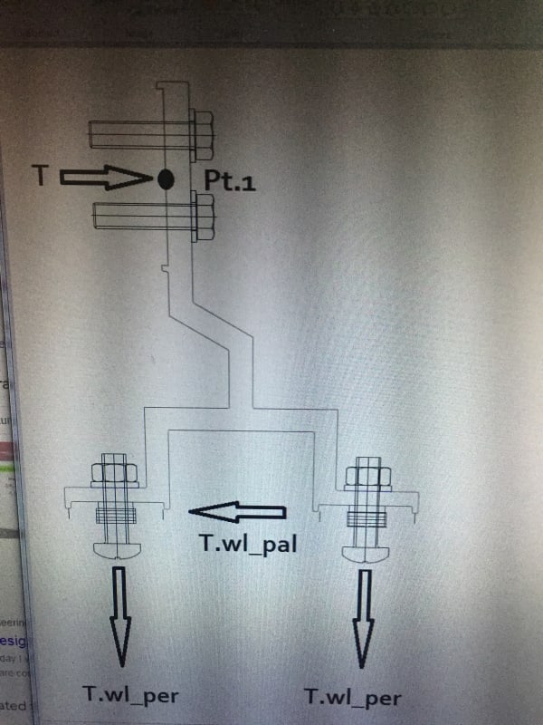
I am in need of assistance. I have this bracket (attached picture) with corresponding loads. I need to get the bending stress of bracket and the tension stress at pt.1. Will there be a couple moment? And if so, how can I apply it in getting the stresses?

A sketch would be very helpful.
Thank you.

IMG_0432_fbbxf9.jpg
 
Replies continue below

Recommended for you

Something like

image_k8oxow.png


Moments in horiz bot leg are vertical force x distance from fastener. Moments in vert bot leg are vert force * distance +/- horiz force at each leg * distance up from connection line. Bottom M = T x shouldn't be there... and vertical force on right side is in opposite direction.

Rather than think climate change and the corona virus as science, think of it as the wrath of God. Feel any better?

-Dik
 
Dear Mr ,dik (Structural),

This approach is not always true. Validation of this approach requires , the moment developing at cantilever bracket shall be single curvature. This can be justified by ; the supported eq,beam.. shall be flexible or the free to rotate without resisting the tip rotation of bracket.

Consider a rigid eq. supported by two brackets. Double curvature will develop and a zero moment point at L/2. In this case , the moment developing at bottom will be M=T*(H/2) and axial force ( for this side compression ) P= T*(B/2) B is span of eq.

This force will act as shear to point 1 (Pt1) and the moment developing at Pt1 will be M=T*(H/2). The tension force developing at upper bolt will be , Ft= M/d ( d is the distance between two upper bolts.
 

Correct... but the rigidities of the attachments will diminish the design moments and deflections... was intended as a simple solution. The only real way to address the cross-section is to do a FEM study.

Rather than think climate change and the corona virus as science, think of it as the wrath of God. Feel any better?

-Dik
 
ΣFx = 0, T = -Twl_pal.
 
first, draw a free body diagram ! If you don't know what a free body diagram is, please look it up. This will show you the "issues" with the original sketch of loads.

the upper bolts (at pt1) react the vertical loads applied (in shear),
they also react the applied horizontal load (in tension or "compression"),
and they develop a couple (to react the moment due to offset load).

another day in paradise, or is paradise one day closer ?
 
Watch out, the fin plate can be quite flexible, thus rigid body assumption/mechanics may not be applicable. A trick problem without more information on the properties of the material, the source and the points of the applied loads.
 
if the load is coming in at the bottom and going out the top then there's not much flexibility will do … other than overload the part internally. Sure, there'll need to be in-plane webs around the kink, but that's "just" detail design.

another day in paradise, or is paradise one day closer ?
 
Status
Not open for further replies.

Part and Inventory Search

Sponsor