mariyan.vt
Student
- Jul 19, 2025
- 1
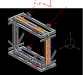
Hello everyone. I am trying to study on structural analysis and FEA. Thus, I have taken already existing design and trying to solve the problem on my own.
The design consists of a frame structure made of different steel profiles. The load is applied where equipment is placed (red arrows). Bolted connections are show with blue arrows. Every other connection is welded. The structure is placed on the floor. Moreover, welded cubes will be placed on each corner to prevent X and Y sliding. My aim is to investigate the overall structural integrity of the structure and also whether the bolted connections are strong enough.
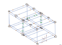
My approach is to simplify the system and represent it as a frame FEA model, find the reactions in the bolted connections and the "beds" where the weight is acting, and do another FEA but with solid elements in the local areas of interest plus hand calculations.
Boundary conditions: 1 node in the 4 bottom corners is constraint in X,Y,Z translational, 1 is constraint in X,Y and the other 2 in Z only. What i struggle with is how to represent the bolted connections shown with blue with constraints ?
Moreover, since the bolted connections in the middle and on the sides of the frame, shown in orange, are on profiles welded to the main profile, is it plausible to represent it as elements (but rotated 90deg) as shown as green lines in the sketch (2nd picture).
Thank you very much.


