Continue to Site

Eng-Tips is the largest engineering community on the Internet

Intelligent Work Forums for Engineering Professionals

  • Congratulations cowski on being selected by the Eng-Tips community for having the most helpful posts in the forums last week. Way to Go!

Effective weight of soil, based on degree of saturation 5

Status
Not open for further replies.

LR11

Structural
Sep 13, 2001
166
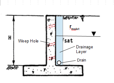
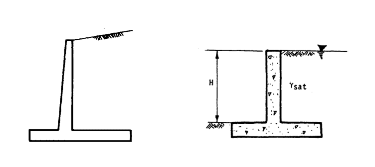
I'm looking at a retaining wall with a heel on the fill side, the heel aids significantly in sliding and rotation stability, because of the weight of the soil. I've read a number of texts to try and determine to what extent the degree of saturation reduces the effective weight of the soil, but haven't been able to find anything definite.

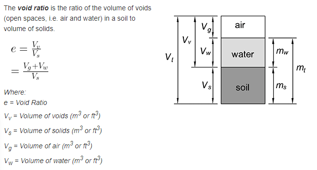
For a fully saturated soil, some texts mention a buoyant condition, ie, uplift. The second image below may be hypothetical, maybe not, but a saturated condition is shown on one side ... see further notes in next paragraph. At the other end of the scale, for a low degree of saturation, I would suggest that the effective weight of soil increases.

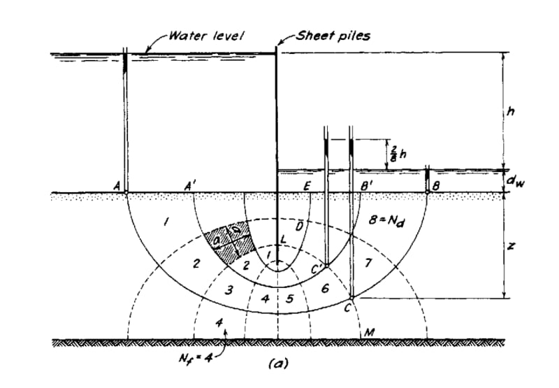
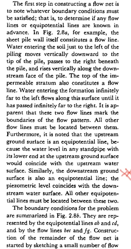
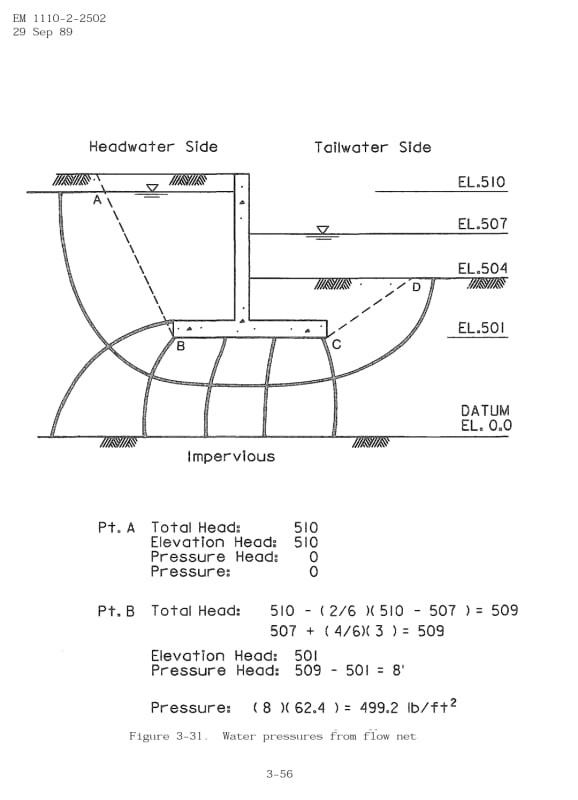
The closes I've gotten so far ... is from a text called "Foundation Design" by Wayne C. Teng, see attached extract. The text mentions that a rainfall event could cause a saturated condition, if there are no drainage measures. It mentions uplift at the surface of sliding and base of the retaining wall. It then states that you should add drainage measures for an economic design. But there is no quantification for the reduced effective soil weight. It does mention flowlines but I'm not really comfortable with extrapolating from these.

So given that I will have a drainage strip and pipe, how could I quantify the effective weight of the soil for a saturated condition.
Has anyone done this using flowlines? Or is there a rule of thumb somewhere, with the soil type as a variable.


RW2_it7u07.png


Replies continue below

Recommended for you

IMHO, you should provide adequate drainage to entirely prevent any hydrostatic surcharge and buoyancy, or if you cannot assure that surcharge and buoyancy will be prevented, then you should design for that possibility, assuming fully saturated soil will occur at the highest expected level and considering that level to generate full hydrostatic pressure, producing full lateral load and buoyancy conditions. I would never attempt to design a retaining wall for partially saturated soils. Soil should be considered as fully dry (for inward rotation design case), and if there is any possibility for saturation, assume that it is fully wet up to the highest expected water level (for outward rotation design case).

 
It must be the COVID that causing you to overthink the design of earth retaining structure. The soil weight is influenced by water/moisture content, but the change has no bearing on the design, as we either use the moist weight, or design for fully saturated condition. For a wall with properly designed drainage system, the water in soil will be drained. The speed of dissipation of pore water pressure (from saturation to moist), thus variation in soil weight depend the soil properties and many other factors, which is too much to discuss in here. But I suggest to start from a review of void ratio and water content, and have an understanding on how soil weight is determined. Here is a starting read.
image_cmb7ul.png


image_fnmpuf.png
 
Theoretically, if there is even the smallest space adjacent to the wall that can fill with water, you will have full hydrostatic loads. It does not depend on the amount of water in the soil. Given equal height of a column of water, a 1"diameter column generates an equal hydrostatic force as a 1000'diameter column.

 
OK thanks for the responses. If I understand correctly, the design would be based on either a drained condition or a saturated condition.

The issue with the saturated condition is that it is uneconomical for a retaining wall with a heel. The buoyancy loads would be more than half the weight of dry soil, the lateral hydrostatic pressure would be more than the lateral earth pressure, the passive effect on the other side is much reduced. All up, your disadvantaged by a factor of at least 4 ... this is assuming saturation is right up to the top of fill, all hypothetical I'm sure.

On another thread, I queried how the lateral pressure increases with a rainfall event. There was a response referring me to the publication DM 7.02 Foundations & Earth Structures. See attached extract. It says that pressures are increased by 20-40% for a cohesionless soil with a vertical drain. If we had designed for a hydrostatic pressure, the increase would be above 100%.
Some data or advice along these lines is what I'm looking for.

r13, I don't think I'm overthinking it, just trying to find out what's really happening. I would suggest very few understand it as it pertains to a real situation. Failures are commonly due to water, at the same time I'm trying to be economical. A rainfall event is tricky because it's short and intense.
 
 https://files.engineering.com/getfile.aspx?folder=0962d707-6b9c-47e8-a28c-2c1429c5f5f3&file=DM_7.02_pp93-95.pdf
Design for ground water on the finished grade is a conservative practice, the need is largely depending on the site conditions.

The buoyancy loads would be more than half the weight of dry soil, the lateral hydrostatic pressure would be more than the lateral earth pressure,....

The total gravity load on the heel may see some change depending on soil density - ϒmoist vs ϒsat, however, the uplift causes headaches. The lateral pressure is most problematic with high groundwater level, so that's why the drainage measure has been emphasized again and again to alleviate the pain. Yeah, I think I couldn't offer much help if you insist on your own course of thinking. Good luck.
 
I've also occasionally looked for a definitive answer to this. I hope you fare better and am following your posts to see where they lead. The published info does not ever seem to tell the whole story and seems contradictory at times, similar to many things with retaining walls (eg active pressure on shear key). Lots of me-too books and manuals covering the same basics but almost silence on the big issue with walls. Articles on wall failures alway seem to say 'after heavy rain' so you'd think it would have been tackled by now. I suspect many walls are unintentionally deep into their factor of safety (economical).

I like to consider a failed/blocked drain case as many walls survive rainfall until one day they don't. Reduced factor of safety in that case as it is worst credible.
 
Sorry of you took offense r13. I'm not sure what I'm insisting though.
I'm allowing for an increased lateral pressure of 20-40% due to rainfall, not unreasonable.
What I'm having trouble accepting is the buoyancy on the base of the retaining wall. ϒ(moist) vs ϒ(sat) is not a game changer. Buoyancy is, this is the theme of the query.

The texts mention a buoyancy load, I'm not fully accepting it and trying to find an answer.
 
I have trouble with the flow net from Teng (and flow nets in general). Equipotential 9 is at ground level on the low side which is the water level. Why is the pressure there h*gamma_w? Why not zero since it's the water surface? Why no fountain spurting up to top of wall?

Maybe understanding this is the key that's missing from my knowledge.

(That Teng book has some gold nuggets.)
 
I wrote the above before your post came in steveh49.

I was thinking the same thing as the texts do not deal with it .. because it's inherently a difficult subject. You know when something is right though.
The closest I got was the text mentioned above, but there were 2 only one-liners with regard to the uplift, just a mention and no explanation.
 
LR11,

On top of the heel, it supports Ws = ϒ(moist)*h, for moist soil, or Wtot = [(ϒ(sat)-ϒ(water)+ϒ(water)]*h = ((ϒ(buoy)+ϒ(water))*h, for fully saturated soil, the resulting pressures are not drastically different, but, when we consider uplift below the heel, u = ϒ(water)*(h+t), the game changes. So, yes, buoyancy is the problem that causes instability.

Check the direction of the buoyancy load, I suspect it is acting upward against the soil weight.
 
OK thank you.
I'm trying to follow up on other references. If I get to a reasonable answer, I'll post back.
 
steveh49,

You need to review the flow net beneath dam with water in different elevations. The pressure at downstream toe simply is the head differential times the density of the water. Google the word "flow net", you may find useful articles for review.
 
I think maybe I misunderstood Teng's description. This from Peck, Hanson & Thorburn (1974) matches how I expected flow nets to work. On the left side, the water level in a standpipe inserted into the ground would not reach the free water surface outside the standpipe.

Referring back to Teng Fig 4-13(a), the uplift at the toe would be equal to the toe depth * gamma_w plus 1/9 * h * gamma_w. At the heel, it is the same except 4.5/9. This uplift is less severe than hydrostatic (ie buoyancy) based on the retained-side water level alone.

More simply, it's a weighted average pressure depending on how close (measured along the flow line / counting equipotentials) the point in question is to the two boundary water surfaces.


Screenshot_20201224-150343_Box_sh4fm4.jpg


Screenshot_20201224-150759_Box_x0jj2m.jpg
 
Not that I'm comfortable with this but here's what I'm going with:

- For a rainfall event, extrapolation is made from the data in "DM 7.02", which comes from journal article "Contribution to the Analysis of Seepage Effects in Backfills, by Hamilton Gray, 1958". I haven't been able to get hold of the article. The date relates to a a wall embedded in an impervious layer, and the water pressures are normal to the failure plane. For a 45° plane, I come up with an average perpendicular pressure of 0.18γwH and 0.1γwH as a vertical component. Extrapolating to a retaining wall with a footing and impervious layer below the footing, is too difficult, so I've just assumed a vertical pressure of 0.1γwH.
- For a situation where water is retained in a steady state, with water at half-height, the pressures on the base ranges from 0.1γwH to 0.55γwH.

With respect to drainage, I did read something yesterday to the effect of allowing for zero water pressure if you have adequate drainage provisions.
But there is debate with this. It seems to be the most important aspect.

I'm going to assume an average uplift pressure of 0.3γwH for now.


What I wrote above for pressure along the flow path isn't quite right. See image below which has the USACE reference number at top left - nice and clear. That document also has an approximation that doesn't require drawing the flow net. Worth reading.


Screenshot_20201224-205148_Adobe_Acrobat_hhn1pp.jpg


Hamilton Gray 1958 article - I haven't read it yet.

 
OK thank you will do.
Happy holidays to all.
 
LR11 said:
Failures are commonly due to water, at the same time I'm trying to be economical.

Please take the advise: engineering economic should be on the bottom of list on considerations of the design of retaining wall, unless the failure likely will not resulted in injury, lose of life, or costly property damage. Water is difficult to manage, we can only be conservative when dealing with it, and try/do the best to alleviate its impact. beware.
 
R13 said it all. The quoted text there is a contradiction of terms, hence a warning of pursuing false economies.

 
Thanks for the moral support, guys/gals.
 
Status
Not open for further replies.

Part and Inventory Search

Sponsor