Continue to Site

Eng-Tips is the largest engineering community on the Internet

Intelligent Work Forums for Engineering Professionals

  • Congratulations cowski on being selected by the Eng-Tips community for having the most helpful posts in the forums last week. Way to Go!

Dynamic dimensioniing & fixing confusion

Status
Not open for further replies.

DrBwts

Mechanical
Nov 4, 2012
297
My drawing has 4 inner rectangles which all have 2 corners fixed each. I then draw an out rectangle (see picture).

dimension_1_e1ksbf.png


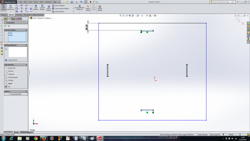
Now it was my understanding that if you fixed a point that meant that it was in fact fixed & could not be moved by subsequent operations.

So I went about dimensioning my outer rectangle but this changed the distances of the 'fixed' rectangles from each other (see picture 2)

dimension_2_zjytgu.png


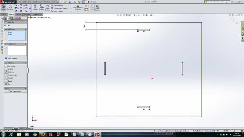
I have also attached the drawing (SW 2014) prior to changing the dimension.

 
Replies continue below

Recommended for you

Not sure what you're seeing but...
I dimensioned from the top small rectangle to the bottom small and between the left and right ones. As expected, they were both driven dimensions. I then changed the 28.20 to 10 and neither of the driven dimensions changed. It would appear to be working correctly. I wonder if it's not just an optical illusion.

Jeff Mirisola, CSWE
My Blog
 
If you zoom in on the 2 pictures you can see that the dimensions (on the bottom status bar) in both picture is different.
 
Yeah, not seeing it on my machine. Normal distance remains 314mm, total length 93.48mm.

Jeff Mirisola, CSWE
My Blog
 
OK thanks for taking the time, back to dimensioning everything :D
 
Status
Not open for further replies.

Part and Inventory Search

Sponsor