Continue to Site

Eng-Tips is the largest engineering community on the Internet

Intelligent Work Forums for Engineering Professionals

  • Congratulations 3DDave on being selected by the Eng-Tips community for having the most helpful posts in the forums last week. Way to Go!

Discontinuous Load Path

Status
Not open for further replies.

Samwise Gamgee

Structural
Oct 7, 2021
118
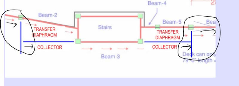
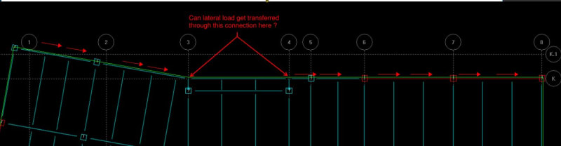
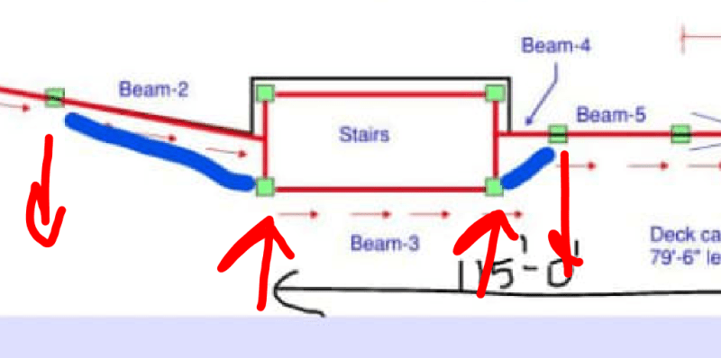
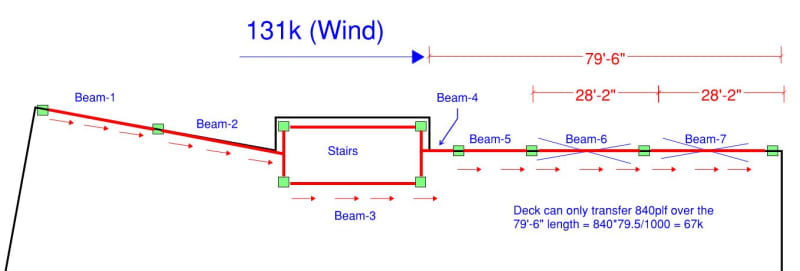
I am trying to resolve forces in the braced frames on roof. Unfortunately the deck does not have enough capacity to transfer shear over the braced frames, so I have to rely on beams in other bays to act as collector elements. However the beams are not in the same straight line to transfer the load into the braced frames due to stairs in the middle. How do I provide a continuous load path from Beam-2 to Beam-3 and from Beam -3 to Beam-4 ? (Attached a screenshot)

Load_Path_gzhkbl.jpg


The only other solution is to place side lap fasteners as close as 3" to increase the shear capacity and drag all of that load in the braced frames. But this is very expensive.
 
Replies continue below

Recommended for you

Expensive doesn't actually mean unnecessary.

I would, however, look at whether or not your "T" sections of beams can be used as elements to spread the load to the other side. IE: You will still collect load at the inboard side of the stairs, but what has been collected can be shared to the other side, lessening the load on the floor.
 
One option that would appeal to me is to create a transfer diaphragm system that would pass the collector load around the stair shaft.

c01_kgdyw1.png
 
The use of transfer diaphragms seems to be a very practical concept to achieve the desired result.

BA
 
I like the concept of transfer diaphragm. However, how is load get dragged from the Collector to the braced frame ? (As they are not in the same line) I have clouded this in the picture with a black cloud

Load_Path_ukde1o.jpg
 
The transfer diaphragm itself. Your large diaphragm will dump its load into the collectors - blue and the interior stair wall. Then the blue collectors will put it into the transfer diaphragms. So the unit shear in the main diaphragm is small, but the unit shear in the transfer diaphragm is very high. It allows you to concentrate the heavy diaphragm construction into a smaller, well defined area to increase overall economy.
 
Well - the one on the right, anyway. Looks like the one on the left doesn't have a braced frame, so it would be putting its load into the main diaphragm, and then the cumulative load in the main diaphragm would go around to the transfer on the right and into the braced frame.

 
More than one way to skin the cat, how about instead of a transfer diaphragm, you just put a plan brace strut between the lower column and upper column. How much more of your diaphragm do you need to engage?
Screenshot_2021-10-21_140635_rxmpbm.png
 
I might be able to make it work with 115'-0" which would be from Beam-3 to Beam-7 with a 1/2" In seam Weld. I was thinking about adding a beam like you have shown between the upper and lower column to provide a continuous load path. Would that suffice or what did you mean by plan brace strut ?

1_hkcnp0.jpg
 
we're looking at a plan view (yes?). do the stairs make a change in elevation ? or are they stairs up onto the deck ?

i think there are ways to integrate the structural beams into these stairs, that may be less invasive (and destructive) to the loadpath.

another day in paradise, or is paradise one day closer ?
 
yeah a beam. that sees likely more compression load than it does bending. To me that solution is likely simpler to construct and design than a series of collectors, struts and transfer diaphragms.
 
Yes, it is a plan view . And I misinterpreted the stair interference. Fortunately the stair framing is lower than the roof. So I believe I had a continuous load path now, but I am still not sure if I can transfer the thru force without having columns at the locations. Please see the screenshot.

1_bwrcbe.jpg
 
Why couldn't you put the load through the connection? I don't see an issue with that.
 
jayrod12 said:
To me that solution is likely simpler to construct and design than a series of collectors, struts and transfer diaphragms.

In many instances, I would disagree for two reasons:

1) You still have to deal with the forces shown below which will add complications of their own.

2) Those struts will usually wind up being short elements placed between the primary gravity members. It tends to make for a lot of annoying, mission critical connections between the struts and the supporting OWSJ etc.

c01_oljlxz.png
 
OP said:
So I believe I had a continuous load path now, but I am still not sure if I can transfer the thru force without having columns at the locations.

What you need is the ability to handle this force at the knuckle
c01_wjmyg1.png
and carry in through the building properly.
 
I agree with your concerns koot, and I've never had the magnitude of Wind load he's describing, but I've always just detailed this to get dumped into the joists etc. It's not that big of a deal as long as you're attentive to the load path and statics (which I'm fairly sure is the whole crux of our job, second only to protect the public)
 
jayrod12 said:
I agree with your concerns koot..

That's a shame because I retract them. In many instance, my approach will also the same two features that I criticized your system for having.
 
They're still concerns, regardless of which method. I just feel my way has less other things to deal with than the transfer diaphragm idea. I'd bet in the end the actual work and load transfer is the same, you're just trading a transfer diaphragm for a hunk of steel.
 
So right now with this setup, I will have a horizontal and a vertical component of force from the beamline that is at an angle. The horizontal load gets transferred to the next collector and into the brace, while the vertical component acts as axial force for the cantilevered members. As long as I check this connection to resist that vertical/axial force, I should be good right ?


1_fuzimm.jpg
 
Status
Not open for further replies.

Part and Inventory Search

Sponsor