Continue to Site

Eng-Tips is the largest engineering community on the Internet

Intelligent Work Forums for Engineering Professionals

  • Congratulations cowski on being selected by the Eng-Tips community for having the most helpful posts in the forums last week. Way to Go!

Dimensioning and Tolerancing of Flexible Parts

Status
Not open for further replies.

lwealing

Mechanical
Dec 27, 2011
17
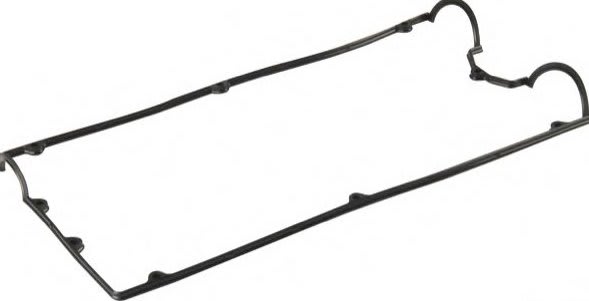
Does anyone have any recommended resources (specialty standards, guide books, etc) that explains the best practices for dimensioning and tolerancing flexible parts such as seals and gaskets? We use ASME Y14.5-2009 as our standard for rigid and nonrigid parts (subject to free state variation - like sheet metal parts, etc) but do not have any guidelines when it comes to extremely flexible molded or extruded parts, especially in elastomer type materials.

We commonly run into issues when engineers create drawings for these types of parts and use profile tolerances and other form controls. Inspection to the dimensional specification can be a challenge due to their flexible nature. Any advice or tips?
 
Replies continue below

Recommended for you

One of the possibilities is is to create the fixture that actually simulates some or all working conditions and see how well the part fits. Sometimes simple go-no go gauges may do the trick.

Another, although not always feasible, is to use methods that are not actually touching the parts, like scanning.

As I know very little about your parts, it is hard to be specific.

I am having similar problems at work myself. Unfortunately I work with people who see no problem taking a caliper to the part with structural integrity of a gummy bear.

I am very curious what others have to say.

"For every expert there is an equal and opposite expert"
Arthur C. Clarke Profiles of the future

 
CH,
I know you are an ISO guy, but does ISO GPS offer more details on how to treat flexible parts versus limited coverage offered by ASME?
I am asking because ISO GPS is known for the care they take for the product / mathematical definition robustness.
 
Thank you greenimi, I am flattered. :)
I am not that much an ISO guy, especially now, when it's hard to follow ever-changing standards.
The problem here is hanging between disciplines - what and how specify on the drawing AND how to measure it.

Say, I put Profile on the drawing - how to control it reliably?
Or - I came up with fancy way to check the part - how to document it on the drawing?

So ISO or ASME - how you measure jellyfish?

"For every expert there is an equal and opposite expert"
Arthur C. Clarke Profiles of the future

 
CH - I agree with your same sentiments. Just having a look for say a simple o-ring, we can refer to ISO 3601-1 Annex B.

Measurement of cross-section dimension:
[ul]
[li]micrometer (ball type anvils)[/li]
[li]vernier calipers[/li]
[li]optical comparitor[/li]
[li]rotating-type fixture with dial indicator[/li]
[li]visual or laser dimensioning equipment[/li]
[/ul]

Measurement of inside diameter:
[ul]
[li]go/no-go lug gage[/li]
[li]flat plug gage[/li]
[li]calibrated or tapered-stepped gage[/li]
[li]traveling microscope[/li]
[li]optical comparitor or a video system[/li]
[/ul]

Could these general rules for o-rings be applied in a way to work for more complex parts like a radial ball bearing rubber seals with complex lip geometry? Is it possible to use line profile tolerance zone and either an optical comparitor or other visual (non-contact) equipment to verify the cross section meets some certain dimensional requirements? If so - then I could imagine a line profile tolerance might serve as a good (and verifiable) way to define the allowable variation. Thoughts??
 
For some pieces we use conical gauges similar to "sizing cones" but with sharper angle.
We consider the measurements accurate, even though we understand the seal stretches a bit. I guess, you just find the measurement that produces the working part.
It is perfectly legal to reference QC procedure on the drawing, like "CHECK INSIDE DIAMETER PER ABC123", so document the description of what you do.
Sometimes I measure some thickness with tube micrometer (rounded anvils) with really loose ratchet, but I understand results are not fully repeatable, so it's more like "reference".
Like I said, I don't have all the answers, so I am really curious what others have to say.

"For every expert there is an equal and opposite expert"
Arthur C. Clarke Profiles of the future

 
I think the o-ring guidelines work well for certain parts sharing a similar symmetric profile.

A plug or tapered/stepped gauge has the advantage of allowing the part to conform to an "ideal" shape. It occurs to me that even with an optical/scanning method there is the issue of distortion even when simply laying it on a surface for scanning. This is probably minimized with relatively small or regularly shaped flat or symmetric shapes, but imagine trying to arrange a large gasket with a very complex profile and a small cross section for scanning - perhaps something like the below. I'm interested to see if anyone knows of any accepted standards or methods for measurement - I suspect most places have developed such standards internally.

gasket_ztfmv7.jpg
 
Ideally I think there would be a fitting algorithm that would scan the flexible part in free state and then fit it to an ideal profile and tolerance - with some applied amount of acceptable elastic deformation. I wonder if anyone has developed this.
 
CheckerHater said:
One of the possibilities is is to create the fixture that actually simulates some or all working conditions and see how well the part fits. Sometimes simple go-no go gauges may do the trick.

If you get a chance, take a look at B.3.5:

"Other methods may be used to determine the inside diameters of larger O-rings after the cross-sectional and parting line projection dimensions have been verified and found to be within tolerance limits, such as a flat gauge with a predetermined rectangular groove that has an inside diameter equal to the minimum O-ring inside diameter and an outside diameter equal to the maximum O-ring inside diameter plus twice the maximum cross-section dimension. The depth of the groove shall be at least 50 % of the cross-section diameter, but no more than the cross-section diameter. If the O-ring falls into the predetermined groove without stretching, then it shall be considered to be within tolerance."

Could this same gage concept be used for more complex shapes like the gasket chez311 posted?
 
For what is worth and since the OP asked for additional material, here is a book writen by James Meadows:

I DO NOT work for him. I am just trying to help (if possible). It is up to the OP to decide if the investment in the book is appropriate in his/her case.
Geometric Dimensioning and Tolerancing Handbook: Applications, Analysis & Measurement

Author(s)/Editor(s):

James D. Meadows
.
Published:
2009
.
DOI:
10.1115/1.802166
Chapter 18
Flexible Parts
Page Count: 14
Abstract
Excerpt
Readers will learn:

1. To tolerance flexible parts.

2. The difficulties in fixturing and inspecting flexible parts to collect repeatable measurement data.

3. About free state variation.

4. That part should be inspected in the way that they function.

5. To apply temporary datum features for in-process inspection.

6. Common misconceptions regarding the tolerancing and inspection of flexible parts.

7. The criteria for selecting datum features on flexible parts.

8. The “free state” symbol and what it means.

9. How to write a “restrained state” note.

10. That all parts are to be measured in the free state, unless restraint applied does not distort measurements, or unless a note is written to allow inspection in the restrained condition.

11. To dimension and tolerance a fixture for simulate datum features for inspection.

12. How to apply and fixture “step datums”.

13. How to use multiple slot centerplanes to create a datum reference frame.

14. The most popular and effective datum scheme for tolerancing sheet metal panels.

-Flexible Parts and Inspecting Them in the Way They Work
-Temporary Datum Features
-Common Misconceptions
-Free State Variation in Sheet Metal Parts
-Specifying Restrained State Inspection
-Fixturing Sheet Metal Parts
-Profile ALL OVER Controls and What They Mean
 
lwealing,

You are in a situation where guidelines do not help. You need to go back to the basic principle that your drawing specifies what you need to do to make your assembly and your product work.

When I prepare a drawing of a plate or of a flat sheet, more often than not, I apply the primary datum to one face, and I apply a note stating that the datum applies when the part is clamped to a flat reference surface. If the part will not be forced flat upon assembly, I do[ ]not apply this note.

Generally, your datums should simulate how your part will be installed and attached. Pretend for the moment that you are applying GD&T to a cable. At one end of the cable, you set up datums that locate the connector in six degrees of freedom. At the other end, you have datums that set that connector up in six different, unrelated DsOF. A sheet metal bracket may see two faces forced perpendicular to each other upon assembly.

In general, if the part is flexible, you need to describe how it is to be clampled.

--
JHG
 
Status
Not open for further replies.

Part and Inventory Search

Sponsor