Continue to Site

Eng-Tips is the largest engineering community on the Internet

Intelligent Work Forums for Engineering Professionals

  • Congratulations cowski on being selected by the Eng-Tips community for having the most helpful posts in the forums last week. Way to Go!

Dimension tolerances 1

Status
Not open for further replies.

pyromech

Mechanical
Jul 30, 2008
39
Folks

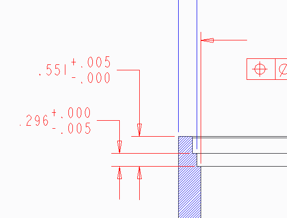
I always had trouble interpreting a cut vs protrusion. In Figure 1, the step feature has a dimension 0.296 -0.005". Wouldn't this cut read 0.296+0.005". The same for Figure 2. It boils down how is machined. Does anyone have a references to read? any tips.

Figure1_ua6xz5.png

 
Replies continue below

Recommended for you

I don't know why you're wondering about protrusion vs cut, or even where that comes into relevance in assigning unilateral tolerances. Maybe I could answer more directly if I understood.

Regardless, no, 0.296 +0/-.005 would absolutely never be read as 0.296 +.005/0 because that's a completely different set of acceptable values.

It doesn't matter if it's cast, forged, welded, bored, milled, punched, or spun and finger-shaped from clay by the ghost of Patrick Swayze.

The acceptable values for that dimension are between the 0.296 maximum, and 0.291 minimum.

Assigning the tolerances on those dimensions has only to do with the design, assembly, or functional requirements which can not be certain to me from what is presented.
 
For cuts, you cant add material back. Say that 0.551 is the diameter hole, then the tolerance is correct. You cant never have 0.551-0.005. Since that step is a cut, i would imagine same rule applies
 
That's...

That's just not how this works.

At all.
 
pyromech,

My interpretation is that the designer wants the depth to be from .291 to .296". There are no rules for which direction tolerances should go. The machinist's job is to hit the dimensions, as specified.

--
JHG
 
Whether or not the cut is an ID, OD, counterbore, or boss has nothing to do with how the dimensions and tolerances are expressed. Regarding stacked limit dimensions, the standard says that with stacked dimensions, the larger value goes on top and the lower on bottom (para. 2.2(a) in the 2009 standard). No consideration is given to whether it's and ID or OD. While the current version of the standard doesn't address the order in which stacked tolerances appear, the draft of the new version does have it delineated.


John Acosta, GDTP Senior Level
Manufacturing Engineering Tech
 
Some organizations like for material removal operations that the nominal number value be the first one a machinist would hit and the tolerance allow for more material to be removed after that.

It's not a requirement of any standard, just a local preference.

External features would be nominal +0/- tolerance; internal ones nominal +tolerance/-0.

Processes such as EDM will want the kerf of the process to be taken into account.

None of these need to be taken into account on the engineering drawing but should be considered for manufacturing process drawings.
 
John,
Would you please at least hint to what's new for stacked tolerances order?

"For every expert there is an equal and opposite expert"
Arthur C. Clarke Profiles of the future

 
@3DDave

I've heard similar before, and also heard opposite, and also heard that they should always be bilateral +/- tolerances so there's no mistaking where to 'hit it in the middle'.

No one is more correct than another. It's all illogical crap to suit someone's particular flavor. It's not something particular to a process; it's a request specific only to a /person/ and so I don't really respect it at all as any form of legitimate practice.

My personal experience is that ideas like that are typically to make up for lazy or incompetent machinists or simple bad practices in programming or tool settings.

ETA: And yes, I have programmed, set up, and ran machines from various drawings.
 

JNieman - that's why I prefer to use +/+ tolerances or -/- tolerances. 2 +12.03/+11.97, for example. Makes them think.
 
Dave,

When you say that it isn't a requirement of any standard do you mean that since Y14.5 is a voluntary standard that nothing in it is a requirement? If so then I agree, but if you're saying that the order that stacked limit dimensions should appear isn't addressed, then I refer you to 2.2(a) of the 2009 standard.

CH,

It currently places the plus value above the minus value and in the case of one of them being a nil value, the nil value will have the opposite sign of the non-zero value for inch tolerancing. All the illustrations show the plus value above the minus value and the nil value with the opposite sign of the non-zero value but no verbage locks it in that way. Of course since this is still in draft, it could change but I hope not.

John Acosta, GDTP Senior Level
Manufacturing Engineering Tech
 
The OP has no stacked limit dimensions, nor did I comment on them. I only referred to nominal values and tolerances applied to them.
 
3DDave, of course, if you are calling out for an interference or sliding fit hole, you likely already do -/- or +/+ tolerancing.

But I like the 2 +12.03/+11.97. I might do that on the print I whip up for someone that wants a quick jig laid out, just to screw with them :)
 
In that case 2.2(a) also addresses limits expressed in a single line as in your 20:59 post. Low value first, then high.

John Acosta, GDTP Senior Level
Manufacturing Engineering Tech
 
20:59 isn't a limits dimension. It's "Two, plus twelve point oh-three, plus eleven point nine seven"

I still don't know why or how 'limits' dims ever entered the convo.
 
Okay, sorry to have chimed in. All I was getting at is that according to Y14.5, whether a dimension is OD, ID, or otherwise has nothing to do with how dimensions and tolerances are expressed.


John Acosta, GDTP Senior Level
Manufacturing Engineering Tech
 
3DDave said:
Some organizations like for material removal operations that the nominal number value be the first one a machinist would hit and the tolerance allow for more material to be removed after that.
...

Given that machine shops want my CAD model or a DXF of my drawing, I would prefer that the dimension shows the actual as-modelled size of the feature.

--
JHG
 
I think a lot of this could be ironed out if the original drawing made use of the dimension origin symbol. It's confusing right now because we don't know what is being measured from what.

John-Paul Belanger
Certified Sr. GD&T Professional
Geometric Learning Systems
 
JP - profile and a datum reference frame would do wonders as well.
 
Belanger,

I think it would be weird to see a dimension origin symbol starting at the bottom of the hole. Maybe it is just me. I find the OPs drawings to be completely interpretable.

In general, when I dimension features like this, I use the top as the origin. The tolerances, as shown, do not support that scheme. The distance from the bottom of the hole to the feature, seems to be critical. If I saw the design, I might disagree with the drawing. My first assumption has to be that the designer/drafter thought this through, and that they know what they are doing.

--
JHG
 
Status
Not open for further replies.

Part and Inventory Search

Sponsor