Continue to Site

Eng-Tips is the largest engineering community on the Internet

Intelligent Work Forums for Engineering Professionals

  • Congratulations cowski on being selected by the Eng-Tips community for having the most helpful posts in the forums last week. Way to Go!

Diaphragm transfer forces

mferg318

Structural
Oct 26, 2017
16
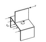
How is everyone handling transfer forces from discontinuous shear walls above a diaphragm, similar to the situation shown below? I'm specifically looking for how to incorporate the shear wall loads into the shear diagram for the diaphragm. Are you adding them as point loads, or distributing across the width of the diaphragm? There seems to be mixed opinions in the literature.
1746201194166.png
 
Replies continue below

Recommended for you

Point load all day long.

If it's flexible, the diaphragm deflection will be sufficient to dump the vast majority of it into the closest shear walls.

If it's rigid, the point load will more accurately capture any local torsional effects at that level.
 
If we are talking about the in-plane shear component of the shear wall, then I add them as point loads and factor them by overstrength factor.

If there is a full length collector I see no reason to shorten the length of the load application.

I think ASCE7-16 Sections 12.10.1.1 and 12.10.2.1 Are fairly clear that the transfer force needs to be scaled up.
 
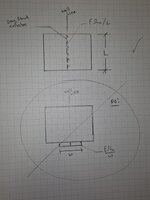
After reading Pham's reply alongside mine I think a sketch is useful

The first sketch shows what I was saying about full length collector, full depth load application. For a 2d diaphragm model, this is the same thing as a point load.

Second case shows what I think you were proposing as an alternative (spreading the load of the width), I don't think that very accurate and seems like a strange step to me.

1000004276.jpg
 
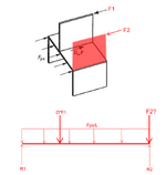
What about the situation where we also have a shear wall directly above a lower wall, but supported by the diaphragm? Are we considering this in the design of the diaphragm, or is it more of a direct transfer to the wall below?

1746205158797.png
 
Pardon my ignorance, but I was under the impression after speaking with coworkers that shearwalls needed to be continuous full height? Maybe this is some weird NBCC requirement or for buildings larger that 2 storeys.

I understand that mathematically you can do this, it's no different than a point load on a deep beam, but do codes allow this?

We transfer lateral loads around all the time, can you confirm where you've seen this requirement that they're full height? The AHJ has never flagged that as a concern. That being said, it may be a part 9 requirement only and our projects are all submitted as engineered solutions as opposed to prescriptive.
 
@mferg318 for your last question, look at the FBD you drew. Solve for the reactions and shears in your diaphragm and see what it tells you.
 
@mferg318 I think your question is more of a detailing question. If the shear wall is continuous up through each story and the diaphragm frames into the side of it, then the diaphragm would not need to consider the load from F2.

If for some reason there is not true continuity between each floor of the shear wall and for whatever reason the load path for the shear in the wall is through the diaphragm then into the shearwall below, then yes you would need to consider this additional load in the diaphragm. This is not a normal situation though.
 
What about the situation where we also have a shear wall directly above a lower wall, but supported by the diaphragm? Are we considering this in the design of the diaphragm, or is it more of a direct transfer to the wall below?

Depends on whether the diaphragm is flexible or rigid. If flexible, the reaction from the wall above will flow straight down into the wall below. If rigid, all of the wall reactions from above get thrown back into the floor and are redistributed to the walls below based on relative stiffness. The difference between the wall reaction below and the wall reaction above is a transfer force. They are often ignored for regular buildings with similar length shear walls that go full-height, but they can be significant when walls of varying lengths are used or when wall openings are introduced.
 
We transfer lateral loads around all the time, can you confirm where you've seen this requirement that they're full height? The AHJ has never flagged that as a concern. That being said, it may be a part 9 requirement only and our projects are all submitted as engineered solutions as opposed to prescriptive.
We do our design to part 4. This is just something I have been told by coworkers to follow, but I've never found a code reason for it.

I guess with the shearwall in the middle of the diaphragm, if you also had shearwalls say at 3rd points, then for assigning load based on stiffness you'd need to include the differential deflection of the diaphragms.

Maybe it's just a lot more simple of a problem to deal with of they all align, and that's why we've stuck to it.
 
@mferg318 I think your question is more of a detailing question. If the shear wall is continuous up through each story and the diaphragm frames into the side of it, then the diaphragm would not need to consider the load from F2.

If for some reason there is not true continuity between each floor of the shear wall and for whatever reason the load path for the shear in the wall is through the diaphragm then into the shearwall below, then yes you would need to consider this additional load in the diaphragm. This is not a normal situation though.
But even if you have a continuous shear wall, the diaphragm would be tied in to the wall in some way (shelf angle or similar). So wouldn't load from the shear wall above still make it into the diaphragm?
 
But even if you have a continuous shear wall, the diaphragm would be tied in to the wall in some way (shelf angle or similar). So wouldn't load from the shear wall above still make it into the diaphragm?
Load gets attracted to stiffer elements. The only reason it would enter the diaphragm in that case is if the shearwall on the other side of the diahragm, and the diaphragm itself for that matter had some ungodly amount of stiffness.
 
Load gets attracted to stiffer elements. The only reason it would enter the diaphragm in that case is if the shearwall on the other side of the diahragm, and the diaphragm itself for that matter had some ungodly amount of stiffness.
If you're designing with a fully rigid diaphragm assumption, then the diaphragm does indeed have an ungodly stiffness...thus some of my confusion. For what it's worth, it feel like diaphragm design in general is one of the most ignored aspects of structural design, doesn't get nearly as much attention as it needs.
 
If you're designing with a fully rigid diaphragm assumption, then the diaphragm does indeed have an ungodly stiffness...thus some of my confusion. For what it's worth, it feel like diaphragm design in general is one of the most ignored aspects of structural design, doesn't get nearly as much attention as it needs.
I mean it doesn't really.

Say for arguments sake it does, then the original wall in question would pick up nothing. So then you basically have a big inverted L shape with a load on the end horizontal leg. The diaphragm might be stiff, but the wall segment would be torqued into oblivion so the assembly itself isn't that stiff. The wall itself is stiff in plane but if you add a rotational load to a single wall it is not ungodly stiff.
 
Let me switch the question up a bit.

I've got a model of the building in question which assumes rigid diaphragm. I keep trying to get the shear in my lower level walls to match the reactions I get by doing a shear diagram for the diaphragm. But now that I think about it, reactions at the shear walls in the model will be different because the loads are being distributed based on the relative stiffnesses of the walls. Does that sound right?
Yes, that does sound correct. Your shear diagram is no longer applicable in a rigid diaphragm scenario as it's viewed as strictly rigid body motion. Shear diagrams only work in flexible diaphragms where conventional statics allows you to determine the reactions.
 
Yes, that does sound correct. Your shear diagram is no longer applicable in a rigid diaphragm scenario as it's viewed as strictly rigid body motion. Shear diagrams only work in flexible diaphragms where conventional statics allows you to determine the reactions.

I disagree here shear and moment diagrams are still applicable to rigid diaphragms, you solve for the wall line reactions via rigid diaphragm analysis then with the known reactions the system is statically determinant.

 
My response was directly related to his proposed scenario. Where he indicated that he was trying to get the reactions to match. I assumed this meant he was trying to use standard beam theory to get the reactions on his diaphragm shear diagram. Which is incorrect.

However, your response is good clarification. There are still shear and moment diagrams, but you do things a bit in reverse for rigid diaphragms versus flexible.
 
I disagree here shear and moment diagrams are still applicable to rigid diaphragms, you solve for the wall line reactions via rigid diaphragm analysis then with the known reactions the system is statically determinant.

This is the approach I was going to default to next. I have the wall reactions from my model and use those in my shear diagram for the diaphragm. As long as loads from used in the model match what I use in the shear diagram, all should work out.
 

Part and Inventory Search

Sponsor