SoFloJoe
Structural
- Apr 3, 2018
- 76
Hi All,
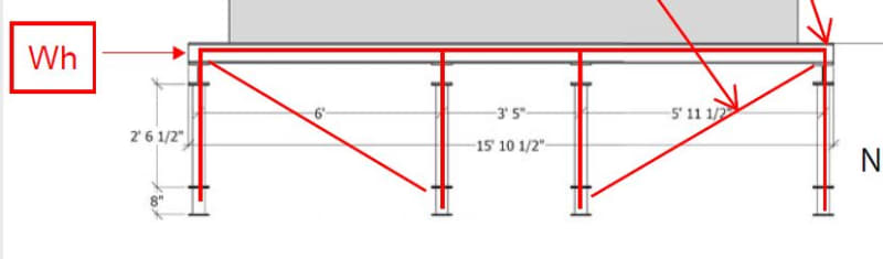
Newbie here! I am working on a structural steel beam system to support a cooling tower. Right now I'm on the column loads, more specifically the flexure design using the AISC equation H1-1b.
I know this was probably covered before (tried searching and did not find what I needed), I need to determine the moment at the top of the column (Mrx & Mry) without using software, where the beam connects. This feels so basic, but cannot find what I need. I used a simple statics (Horizontal Wind Load P x Length) but the moment is too high so I need a more specific method. Can the Euler's formula be reworked to determine moment or deflection? Or rework the Moment diagrams on a beam (Table 3-23 AISC)?
The wind load was already calculated and I used the resultant divided by the tributary area of the worst case support.
Any help here is much appreciated. Thank you!