PaulKraemer
Electrical
Hi,
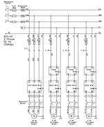
I am trying to troubleshoot a blower drive system that includes a DC drive board [KB Electronics KBCC-255 (9940A)]. The DC drive board controls a 0-180 VDC output to a DC motor that drives a blower. The magnitude of the 0-180 VDC output is determined by a 0-10 VDC signal that the DC drive board receives from a closed loop speed controller. There are three identical blower drive systems on the same machine. Each blower drive system utilizes the same components and is wired the same way. The attached image shows how these components are wired. The drives I am focusing on are the #1, #2, and #3 Supply Blowers.
All three Supply Blower drives were working fine for a long time, but the 15 amp fuse that protects the #2 Supply Blower drive recently started blowing repeatedly. The #1 and #3 Supply Blowers are still working fine.
We were able to get the #2 Supply Blower running by replacing the 15 amp fuse with a 30 amp fuse, and we took some current measurements with a clip-on ammeter while all three blowers were running.
On the #1 and #3 Supply Blowers (which are working fine), we measured very similar current on the line (going into terminal L1) and the neutral (coming out of terminal L2) in the input power circuit for the drive. We also measured very similar current on the output power wires to the motor, one coming from terminal A1 (+) and the other coming from terminal A2 (-).
On the #2 Supply Blower (which is misbehaving), we measured noticeably different current on the line and the neutral of the input power circuit. We also measured noticeably different current on the A1 (+) and the A2(-) output power conductors to the motor. Our exact measurements are shown below....
When we took these measurements, #3 Supply Blower was running at a faster speed than #1 Supply, so the higher current does not surprise me. The seeming imbalance between line and neutral and A1 (+) and A2 (-) on #2 Supply does concern me.
If anyone here can give me an idea what might cause this, I would greatly appreciate it. I'd like to determine if the problem is more likely in the DC drive or external to the DC drive (perhaps the motor and/or the filter through which the input power circuit passes).
Any advice or suggestions will be greatly appreciated.
thanks in advance,
Paul
I am trying to troubleshoot a blower drive system that includes a DC drive board [KB Electronics KBCC-255 (9940A)]. The DC drive board controls a 0-180 VDC output to a DC motor that drives a blower. The magnitude of the 0-180 VDC output is determined by a 0-10 VDC signal that the DC drive board receives from a closed loop speed controller. There are three identical blower drive systems on the same machine. Each blower drive system utilizes the same components and is wired the same way. The attached image shows how these components are wired. The drives I am focusing on are the #1, #2, and #3 Supply Blowers.
All three Supply Blower drives were working fine for a long time, but the 15 amp fuse that protects the #2 Supply Blower drive recently started blowing repeatedly. The #1 and #3 Supply Blowers are still working fine.
We were able to get the #2 Supply Blower running by replacing the 15 amp fuse with a 30 amp fuse, and we took some current measurements with a clip-on ammeter while all three blowers were running.
On the #1 and #3 Supply Blowers (which are working fine), we measured very similar current on the line (going into terminal L1) and the neutral (coming out of terminal L2) in the input power circuit for the drive. We also measured very similar current on the output power wires to the motor, one coming from terminal A1 (+) and the other coming from terminal A2 (-).
On the #2 Supply Blower (which is misbehaving), we measured noticeably different current on the line and the neutral of the input power circuit. We also measured noticeably different current on the A1 (+) and the A2(-) output power conductors to the motor. Our exact measurements are shown below....
| #1 Supply | #2 Supply | #3 Supply | |
| Input Line Current | 1.32 amps | 16.5 amps | 5.4 amps |
| Input Neutral Current | 1.8 amps | 4.5 amps | 4.5 amps |
| Motor A1 (+) Current | 2.4 amps | 4.6 amps | 4.6 amps |
| Motor A2 (-) Current | 2.2 amps | 12 amps | 4.5 amps |
When we took these measurements, #3 Supply Blower was running at a faster speed than #1 Supply, so the higher current does not surprise me. The seeming imbalance between line and neutral and A1 (+) and A2 (-) on #2 Supply does concern me.
If anyone here can give me an idea what might cause this, I would greatly appreciate it. I'd like to determine if the problem is more likely in the DC drive or external to the DC drive (perhaps the motor and/or the filter through which the input power circuit passes).
Any advice or suggestions will be greatly appreciated.
thanks in advance,
Paul

