TiCl4
Chemical
- May 1, 2019
- 631
I have a pressure vessel that has 3 stamped dimpled jacket segments on it. The jackets are all rated to 150 psig. I'd like to walk through my initial sizing methodology and assumptions and get feedback on the assumptions and things I might have missed.
Dimpled Jacket, required relief rate
MAWP: 150 psig @ 400 F
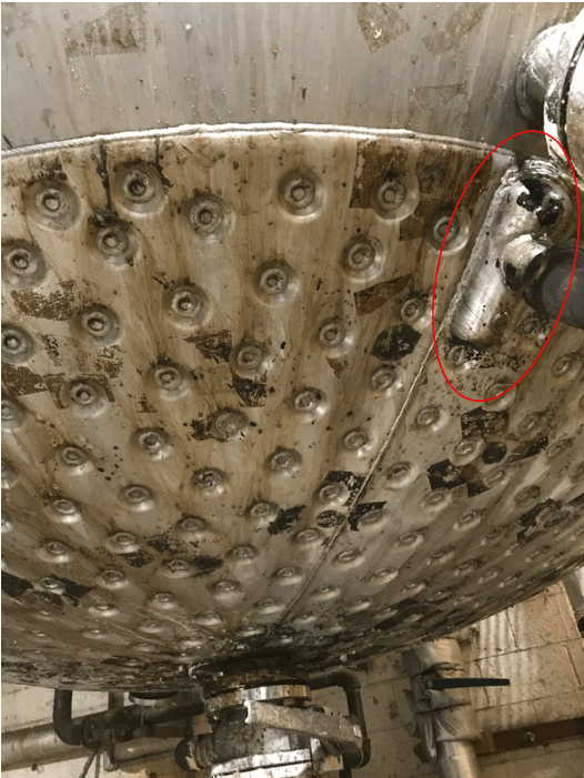
Location: Vessel bottom head.
Diameter: 92". Free passage space for flow is 0.3285"
Contents: Water when cooling, normally 60 psig.
Governing case: Fire, jacket full of water. Interior vessel empty - no credit for vessel contents providing heat sink to jacket. Assuming two-phase flashing saturated liquid flow.
Area, A, exposed to fire: 46.16 sq.ft.
Heat Input: 923,279 BTU/hr (NFPA 30 Eqn B2a, Q = 20,000*A)
Allowable overpressure: 21%
Relieving Pressure: 196.2 psia
Relief to atmosphere through short tailpipe, flow is critical.
Enthalpy of vaporization at relief conditions: 845 BTU/lb
Required relief rate: 1093 lb/hr vapor
Valve Sizing
I chose the two-phase methodology, API 520 C.2.3, due to the initial required flow (after thermal expansion), whereby steam evolving from the heat transfer surfaces will push the hot, saturated liquid to the inlet of the PRV, where it will flash to two-phase flow through the relief valve. Thus the 1,093 lb/hr vapor relief will push out 42.6 gpm of water at saturation conditions. Liquid will be pushed to the PRV initially due to essentially no disengagement space in the jacket. In addition to the nozzle on the picture below, there is an identical nozzle at the bottom of the jacket that I could use to essentially force the relief to be liquid-only. The spreadsheet I used to calculate this is attached.
The result of the calculation is a 0.53 sq.in. orifice
Discussion/Questions
[ul]
[li]This 0.53 sq.in. would call for an API "H" orifice size. However, the ASME "G" orifice has an 0.589 sq.in. orifice size. Would using a "G" orifice be possible if I re-ran the calcs using specific discharge coefficient from a manufacturer?[/li]
[li]For two-phase flow, should a relief valve be a dual-certified relief valve?[/li]
[li]The inlet losses do not appear to exceed 3%. The relief path (see picture below)connection to the jacket is 8" long and 3" wide, for a total area of 7.2 sq.in. The connecting pipe is 2" NPS, and a normal "H" valve that I've found has a 1.5" inlet. At this flow rate, pressure drop is something like 0.15 psi/10 equivalent feet. Comments?[/li]
[li]Lastly, is this exercise even useful? The jacket has an approximate volume of 10 gallons (92" diameter, void space is 0.3285" high), and will likely empty in 5-7 minutes, tops. After that, the vessel will contain vapor at 182 psig, but temperature will continue to climb until equilibrium is reached. I don't see the jacket surviving the combination of fire temps and 182 psig. What's the point of providing overpressure protection if the vessel will fail anyways due to high temperature?[/li]
[li]If the before point/question is valid, should I just document this case in the relief design record and state that the fire case will always result in jacket failure, and just put a much smaller thermal relief valve on the jacket?[/li]
[/ul]
This was a long question. Thank you for your time.
Dimpled Jacket, required relief rate
MAWP: 150 psig @ 400 F
Location: Vessel bottom head.
Diameter: 92". Free passage space for flow is 0.3285"
Contents: Water when cooling, normally 60 psig.
Governing case: Fire, jacket full of water. Interior vessel empty - no credit for vessel contents providing heat sink to jacket. Assuming two-phase flashing saturated liquid flow.
Area, A, exposed to fire: 46.16 sq.ft.
Heat Input: 923,279 BTU/hr (NFPA 30 Eqn B2a, Q = 20,000*A)
Allowable overpressure: 21%
Relieving Pressure: 196.2 psia
Relief to atmosphere through short tailpipe, flow is critical.
Enthalpy of vaporization at relief conditions: 845 BTU/lb
Required relief rate: 1093 lb/hr vapor
Valve Sizing
I chose the two-phase methodology, API 520 C.2.3, due to the initial required flow (after thermal expansion), whereby steam evolving from the heat transfer surfaces will push the hot, saturated liquid to the inlet of the PRV, where it will flash to two-phase flow through the relief valve. Thus the 1,093 lb/hr vapor relief will push out 42.6 gpm of water at saturation conditions. Liquid will be pushed to the PRV initially due to essentially no disengagement space in the jacket. In addition to the nozzle on the picture below, there is an identical nozzle at the bottom of the jacket that I could use to essentially force the relief to be liquid-only. The spreadsheet I used to calculate this is attached.
The result of the calculation is a 0.53 sq.in. orifice
Discussion/Questions
[ul]
[li]This 0.53 sq.in. would call for an API "H" orifice size. However, the ASME "G" orifice has an 0.589 sq.in. orifice size. Would using a "G" orifice be possible if I re-ran the calcs using specific discharge coefficient from a manufacturer?[/li]
[li]For two-phase flow, should a relief valve be a dual-certified relief valve?[/li]
[li]The inlet losses do not appear to exceed 3%. The relief path (see picture below)connection to the jacket is 8" long and 3" wide, for a total area of 7.2 sq.in. The connecting pipe is 2" NPS, and a normal "H" valve that I've found has a 1.5" inlet. At this flow rate, pressure drop is something like 0.15 psi/10 equivalent feet. Comments?[/li]
[li]Lastly, is this exercise even useful? The jacket has an approximate volume of 10 gallons (92" diameter, void space is 0.3285" high), and will likely empty in 5-7 minutes, tops. After that, the vessel will contain vapor at 182 psig, but temperature will continue to climb until equilibrium is reached. I don't see the jacket surviving the combination of fire temps and 182 psig. What's the point of providing overpressure protection if the vessel will fail anyways due to high temperature?[/li]
[li]If the before point/question is valid, should I just document this case in the relief design record and state that the fire case will always result in jacket failure, and just put a much smaller thermal relief valve on the jacket?[/li]
[/ul]
This was a long question. Thank you for your time.