Hello!
So I'm replacing a transmission in a truck and the speed sensor (in the output shaft of each transmission) is not the same.
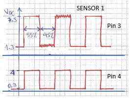
According to my oscilloscope, these are the signals from old speed sensor. (rectangular waves)

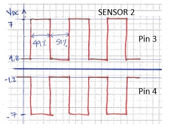
And these are the signals from the new speed sensor. (rectangular waves too)
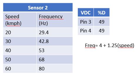
I would like to implement a circuit (perhaps in a protoboard) in order to "translate" the output signal of this new sensor (SENSOR 2) so the ECU can see what it wants to see.
Any suggestions are welcome.
Please your kind help.
Thank you!
So I'm replacing a transmission in a truck and the speed sensor (in the output shaft of each transmission) is not the same.
According to my oscilloscope, these are the signals from old speed sensor. (rectangular waves)
And these are the signals from the new speed sensor. (rectangular waves too)
I would like to implement a circuit (perhaps in a protoboard) in order to "translate" the output signal of this new sensor (SENSOR 2) so the ECU can see what it wants to see.
Any suggestions are welcome.
Please your kind help.
Thank you!