Tek-Tips is the largest IT community on the Internet today!

Members share and learn making Tek-Tips Forums the best source of peer-reviewed technical information on the Internet!

  • Congratulations TugboatEng on being selected by the Eng-Tips community for having the most helpful posts in the forums last week. Way to Go!

Comprehending Transient Hydraulic plots 1

Status
Not open for further replies.

Iomcube

Chemical
Joined
Dec 11, 2015
Messages
187
Location
TR
I have modeled a simple system of single pipe. The upstream is connected to a water reservoir RL(m)=80 & pipe RL(m)=20, Dia(m)=0.6 & Length(m)=5500. The downstream (end connection) is a shut-off valve discharging to atmosphere @ 0.12m^3/s. This valve is simulated to close at 0.01s abruptly

Now I have x2 graphs from which I need to comprehend:

1] Wave reflection time 2L/c ...more about this parameter: 2] System deceleration value

Now please audit if my comprehension is correct
transfer_msekqm.jpg

transfer2_r1xnth.jpg

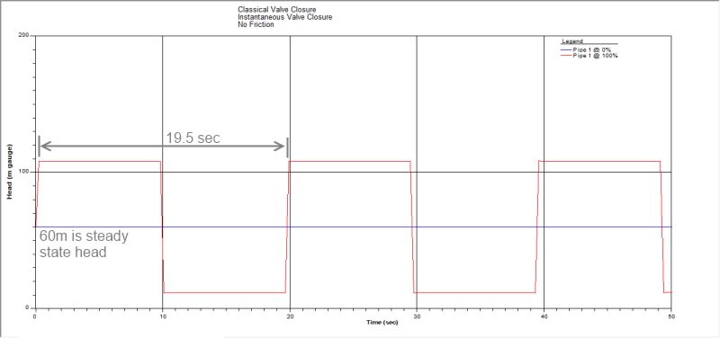
From the 1st plot 2L/c = ~19.5s
so c = (2*5500)/19.5 = 564m/s

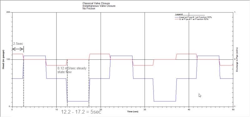
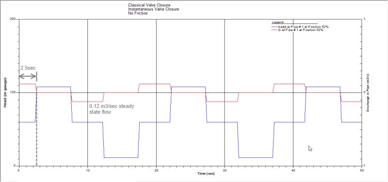
From 2nd plot system deceleration is
0.12/(0.25*pi*0.6^2) = 0.424m/s
0.424/2.5 = 0.17m/s^2
 
I'm not sure what you're doing there.

sonic velocity in water is around 1450m/s, not 564.

“What I told you was true ... from a certain point of view.” - Obi-Wan Kenobi, "Return of the Jedi"
 
ax1e, thanks for your input I had discovered my mistake. 19.5sec, time duration of complete wavelength (if you put it that way) equals 4L/c

From the 1st plot 4L/c = 19.5s
so c = (4*5500)/19.5 = 1128.2m/s

ax1e, you previously said you are versed with transient software. So how do you estimate system deceleration from the plots? Any method of calculating it?
 
1128m/s is still quite a bit slow.
Why not L/c?
I don't really know what you mean by "system deceleration".

“What I told you was true ... from a certain point of view.” - Obi-Wan Kenobi, "Return of the Jedi"
 
Low speed because plots are generated by HYTRAN which was set-up to include 1% air as well as pipe elasticity is also included...
ax1e said:
Why not L/c?
we will do it your way. If you see the diagram at bottom right of You can say that at L/c v=0; that means Q=0. This value can be observed via 2nd plot
transfer2_r1xnth_wvnrsc.jpg

You can observe from graph it's ~5sec from 1st plot it was ~4.875sec

I don't really know what you mean by "system deceleration".
I need this value to study & select check valves as mentioned here
 
In accordance with what I have said previously, when I do a transient analysis, I have to enter a check valve closing time. However flapper closure really occurs over the same period that it takes the reverse flow to move the same distance that the flapper has to move to reach closure. It is the reverse flow rate associated from the pressure wave that forces the flapper to move to the closed poosition, therefore clossure can not occur slower or faster than the reverse flowrate. you might also assume that the surge pressure acts on the flapper and closes it, so you could do a acceleration = force / mass to find the average acceleration on the flapper and solve for velocity and distance traveled during the time period. ?? I have never found it necessary to do anything other than enter the valve closing time.

IMO when the check valve closes, flow has stopped and you essentially have complete deceleration except for some residual waves that only travel back and forth, which I think with isothermal flow and no friction will never stop, however net deceleration (no sustained flow forward or backward) has already completed.

Look at the chart, find the kind of check valve you need for your given flowrate use its closing the time as the deceleration period. Maybe you need to use an iterative solution to find out the answer you're looking for.

“What I told you was true ... from a certain point of view.” - Obi-Wan Kenobi, "Return of the Jedi"
 
I have been reading & comprehending for the past x2 weeks all about surge analysis (COVID-19 leaves). I am new in this so please bear with me.

I have to enter a check valve closing time.
How you judge closing time? Is it a generic value independent of vendor shared information about check valves?

In all of my reading here & there this quantity isn't given to you by vendor rather it's calculated via system deceleration. So in essence what I want to know is check valve closing time (main objective) but to get to this I need deceleration value at say pump trip...


^ p/2 Fig.1 is a typical vendor curve, I am quoting

Calculating the deceleration can be difficult because it is a function of many parameters such as pump inertia (provided by the pump manufacturer), length of the liquid column, friction losses in the piping system and the static head or slope of the pipe. Engineers typically rely on a computer simulation of the system to compute deceleration.
It is the valve manufacturers' responsibility to provide the closing characteristics of their valves so that the engineer can predict the maximum reverse velocity that may occur. For each type of check valve, a response curve should be generated to show the relationship between the deceleration of the liquid column and the maximum reverse velocity through the check valve (Provoost, 1983). The deceleration is expressed in terms of dv/dt, or change in forward velocity, divided by change in time, or fps^2 (m/s2). The reverse velocity is developed from testing and is expressed in velocity terms, or fps (m/s).
 
OK, I'm starting to get that it's a pump trip and pump deceleratiom problem that you are looking at. You're right. I think the C-19 problem must be distracting me too.

found this in my files.

“What I told you was true ... from a certain point of view.” - Obi-Wan Kenobi, "Return of the Jedi"
 
 https://files.engineering.com/getfile.aspx?folder=f7268745-2343-4e52-ab9f-c68472ef9b90&file=dynamic_testing_check_valves.pdf
Extremely thanks sir, your literature is much appreciated
 
ax1e, regarding first attachment dynamic_testing_check_valves.pdf

In the last x2 pages conclusions are drawn based on laboratory test of check valves (developing relationship b/w reverse velocities & system deceleration)

Now there are x2 conclusions

(2) Reverse velocities are greater for valves with larger strokes or travel of components to close.
(4) Reverse velocities will be greater for valve designs with larger flow coefficients.

Now greater reverse velocities translate to bigger surge ...So can we further comprehend that:
point 2 & 4 suggests to have a check valve of NOT the same ID as the pipe line;
employ reducer... this however will increase running (steady state) pressure drops
 
Works for me. Anything that increases potential flow and reduces pressure drop (they go hand in hand) will tend to increase surge.

Everything in engineering design is a trade-off. When you understand the problem well enough you always reach an optimization process. If you don't see the optimization problem, keep studying. Here you want to maximize forward flow, but reduce surge, keep capital and operational costs reasonable, while meeting all design and operational constraints. If you need a pig to run through the check valve, smaller diameters are not an option. Reducers that increase pressure drop will tend to raise the operating pressure, which may also increase max surge pressure.

The true objective of the Empire was to destroy the Death Star because operational and insurance costs jumped to 7.8 octillion USD per day.


ax1e, thanks for your reply.

Now because my reading of SURGE is ongoing & am getting tad OK thanks to this forum! Next thing I want to understand from your experience what are the pitfalls if pumping station is installed with hydro-pneumatic surge tank. These equipment are very much IN in surge prevention & control but I cannot find pros or cons of this equipment
 
I've never had an opportunity to use a h/p surge tank. I have always needed far more surge volume release (min 10,000 bbls or so) to keep pressures under control. I presume that they are useful on smaller systems. Capital costs, extra controls/sensors, larger space allowance and the usual additional operation and maintenance factors would be negative factors, however the benefit is great if it allows you to be able to operate continuously and keep pressures under allowables. Shutting down to prevent surge is not ideal in continuous processes. Hard to make money when you're shut down, so keeping the dollars coming in can be a huge advantage if you have a high lvalue product or a large volume operation.

“What I told you was true ... from a certain point of view.” - Obi-Wan Kenobi, "Return of the Jedi"
 
Status
Not open for further replies.

Part and Inventory Search

Sponsor

Back
Top