Continue to Site

Eng-Tips is the largest engineering community on the Internet

Intelligent Work Forums for Engineering Professionals

  • Congratulations waross on being selected by the Eng-Tips community for having the most helpful posts in the forums last week. Way to Go!

Code design of variable depth girder 2

Status
Not open for further replies.

ALK2415

Structural
Sep 15, 2014
289
Dear Friends,
if you have specific code (ACI, CAN, AS or EN)of design that cover the shear design reinforcement of variable depth beam
thanks in advance for your help ...
variable_depth_beam_kc1jmf.jpg
 
Replies continue below

Recommended for you

How is this different than designing any other concrete beam?

It goes back to first principles. You calculate the demand on the beam and plot how it changes along it's length. Do one for shear and another for moment.

Then use your first principles (based on the geometry and reinforcement at each section) to calculate the member capacity and plot how it changes along it's length. Overlay the shear capacity and demand curves to demonstrate that you're safe. If not, you know where to increase your shear capacity. Do the same thing for the moment capacity and demand curves.

I remember doing something like this in my undergraduate concrete course. It was a single beam (not tapered) with varying reinforcement for shear and moment. But, the concept doesn't really seem like it should be any different for a tapered member.
 
For shear design process of a reinforced concrete beam involves calculating the demand on the beam and plotting how it changes along its length.
Changing the beam depth will change its [load demand and load resistance]. See load-resistance of a reinforced beam depend on its effective depth, which is variable with length.
Since this is done for both shear and moment. And applying equilibrium principles based on the geometry, shear (and longitudinal) reinforcement at each section will be calculated.
the member shear capacity for both concrete and reinforcement (Vc, Vs), which is translated to steel stirrups spacing, could be calculated and plotted along its length.
Actually, steel stirrups spacing derivations is what I'm looking for.
 
@ALK2415 ,

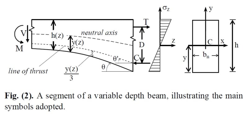
Where did you find the figure that you have posted ? If the question is , how to analize the beam with variable depth, you can follow the basic principles , just apply equilibrium rules for the section . You may STM model the beam ( truss analogy ) similar to EC shear design concept. Pls look figure C section. The shear force will be affected by C and T . ( figure from
Reinforced Concrete Design to Eurocode 2 , Giandomenico Toniolo • Marco di Prisco )

variable_depth_girder_prndis.jpg


If the question is , to look for specific code ACI, EN .. how to analize the beam with variable depth , i am afraid you can not find at the latest editions.This is old concept and you can find at old versions of German code (DIN 1045 ) and SNIP 2.03.01-84_ Concrete and Reinforced Concrete Structures.
I looked my old documents but could not find at first look .


Use it up, wear it out;
Make it do, or do without.

NEW ENGLAND MAXIM
 
Many thanks HTURKAK
picture ware taken from research paper Link
The problem was asked by third person whose beam has different geometry (also variable depth beam). Iam trying to study (develop if possible) the shear reinforcement spacing formula (theory derivations) for such conditions (variable depth and loading).
and again, I highly admire your help and patience ...
 
If it were me, I'd likely be designing it as the shallowest depth for the entire tapered portion. And if it never stops tapering, I'd be doing segmented designs assuming the shallowest depth for each segment. Additional depth only serves to improve performance, and stirrups are cheap.
 
@ jayrod12
Thanks for your inputs, Iam sure that someone done the calculations for such conditions (CODE Commitees)! just can't find it
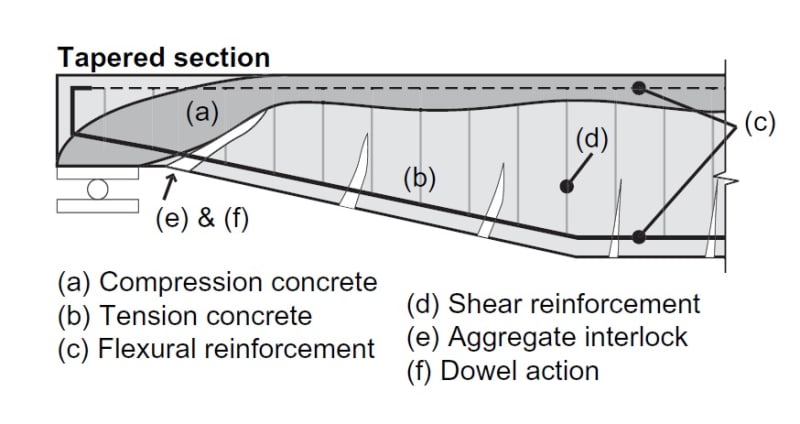
i found similar textbook but for I-section (non-prismatic).
if you Notice this problem exaggerated for Box-girder, which most of them of variable depth
this concept also applies for wooden/lumber girder for calculating the shear resistance or shear flow (bolts spacing ... etc)

variable_depth_beam-02_etqkwz.jpg

from the attached link
Link
 
I tend to program stuff, so I'd write a program that splits the beam into 1000 little pieces and calculates the d, V, and M, and full shear design, at each little piece. It would spit the results into an Excel table. Then you can use Excel (or another program, or a subroutine of the 1000 piece program) to split it into a few sections, like 10' long each. You can even have your program design stirrup spacing and size at each of the 1000 pieces based on a set of selection rules (like use #3 down to 4" spacing, then try #4 down to 4" spacing, and so on) and the second program can grab the highest reinforcement in those sections.

The precursor to this program would be something that calculates V and M based on loading and end conditions, and splits it into an arbitrary number of pieces. I made something for that as well, which took like 2 days, but it's very useful to build off of.

My personal way is to not use formulas and derivations anymore. If you're proficient in scripting/coding, it's less work to just automate it. On the other hand, if the coding skills aren't there, your way with making a new equation would be better. I can see it getting really tricky to slam a varying triangular or parabolic d into the stirrup formula, especially if you use the formula that also includes moment (in ACI code).
 
Many thanks milkshakelake
you read my mind, was of MATLAB to do the subroutine. Also would be very useful to add multiple parameters [fc', gamma, bx, hx ..etc]concrete density [different types Light-normal-heavy] and plot them accordingly. These curve would be a reference line to see best shape variations with/out steel reinforcement.
But derivations would be much simpler also that need to be resolved for different shapes of beam depth variation (concave and convex)
NOTE: these assumptions also applied to hollow section with such void depth variations.
 
Eurocode clause 6.2.1 adds an extra shear component for inclined chords. Figure 6.2 shows it.
 
Status
Not open for further replies.

Part and Inventory Search

Sponsor