Tek-Tips is the largest IT community on the Internet today!

Members share and learn making Tek-Tips Forums the best source of peer-reviewed technical information on the Internet!

  • Congratulations LittleInch on being selected by the Eng-Tips community for having the most helpful posts in the forums last week. Way to Go!

Civiltech Shoring Suite - Determination of slope and moment

LockeBT

Structural
Joined
May 9, 2021
Messages
58
Location
US
Anyone familiar with the Shoring Module and their methodology to come up with the Slope for Soldier Pile? I am checking their output and I want to make sure I can get the same answers myself. However I am running into some trouble coming up with the same slope (and in turn, deflection).

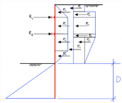
Using the Hinge-Method for soldier pile with multiple braces (per CalTrans) I was able to come up with the same reactions and embedment depth as the program.
Loading.PNG

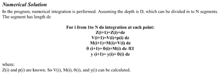
For shear, moment, slope and deflection, the program uses the double-integration method (which is the same as finding area under the curves). Shoring Suite Manual Capture.PNG
Since some of the loading gets complicated (such as the Boussinesq loading curve), integrating those equations at multiple segments gets quite hairy so I used the trapezoidal rule with small segments to approximate. Results for shear and moment were very close as you can see.
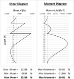
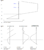
My ResultsShoring Suite Results.PNG

My trouble is going from the moment curve to the slope. There isn't a location along the depth were I can comfortably predict that the slope would be 0 as my starting point. And no, it isn't at where the moment is max.

This has been bugging the hell outa me. Any help is much appreciated.
 
Forgive me, as it's been a while since I've done deflection calculations by hand. Could you not do some calculations around the continuity of the slope above and below the upper brace point?
 
To understand the problem more clearly, could you give all your used inputs, namely lengths between pile reactions, loading, section properties, etc. Knowing all used inputs, gradient and deflection equations can then be derived and boundary conditions applied.
 
Forgive me, as it's been a while since I've done deflection calculations by hand. Could you not do some calculations around the continuity of the slope above and below the upper brace point?
The Hinge Method assumes the top span and the cantilever as its own span, then everything else below is conservatively treated as simply supported spans. As you can see, both the program's and my output of shear and moment reflect that. The slope is only continuous over the 1st brace but not the 2nd brace. Therefore I cannot use the continuity of the slope above and below the lower brace point.
 
Last edited:
To understand the problem more clearly, could you give all your used inputs, namely lengths between pile reactions, loading, section properties, etc. Knowing all used inputs, gradient and deflection equations can then be derived and boundary conditions applied.
I can give you all that separately. However, how are planning to determine slope and deflection? Double integration? The boundary conditions (or locations that we know a sure value of slope) isn't simple as it is with conventional beams. I do not have any boundary condition that can help me with determining slope as they are not zero at either support. It is zero at some point between the 2nd support and the bottom of embedment depth, but not exactly at the peak moment within that span. Therefore I am stuck at coming up with that "boundary" condition.
 
I’m interested to see how the shear force and bending moment equations are derived. The approach I’ve used in the past is by strain energy (SE). I’m wondering if the method can be used in this case. Differentiating the SE w.r.t a point load / moment gives you the deflection / rotation at that point. A zero force / moment anywhere along the beam can also be used. Maybe this method can be used?
 
Last edited:
The Hinge Method assumes the top span and the cantilever as its own span, then everything else below is conservatively treated as simply supported spans. As you can see, both the program's and my output of shear and moment reflect that. The slope is only continuous over the 1st brace but not the 2nd brace. Therefore I cannot use the continuity of the slope above and below the lower brace point.
I referred to the upper brace. Could you not use some condition of slope continuity there?
 

Part and Inventory Search

Sponsor

Back
Top