DoubleStud
Structural
- Jul 6, 2022
- 501
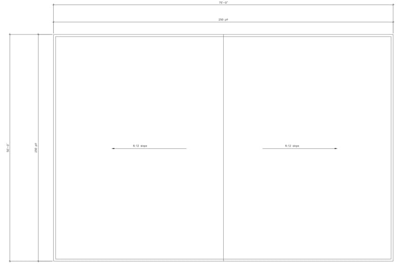
Hey fine folks. Typically I design houses with many interior walls and wall jogs where I am not as worried about lateral forces. Now I am designing a big detached garage with no wall in the middle. I just want to make sure I am not missing anything. For the purpose of this post, I just simplified the dimension and the force. Let's look at the wind blowing North South. I know the load is not suppose to be equally distributed because it is a gable end. I just went to the mid height of the gable and use that height. I use the simplified method from ASCE. Let's just say I have 250 plf.
Based on Table 4.2b of the wind and seismic provision, using minimum 7/16 panel with 8d nail Case 1 can get me 0.5 x 715 = 357.5 plf. OK
Moment = (250 plf x 75^2 )/8 = 175781 LB FT
b = 50 ft
T = C = M/B = 3500 LB
Hem fir #2 tension = 525 psi x 1.6 (duration factor = 840
tension capacity of 2x6 top plate = 1.5x5.5x840 = 6930 lb. 2x6 chord is OK
splice nailing use 16d. Table 11N NDS 16d 1.5" side member on hem-fir #2 = 122 lb x 1.6 (duration factor) = 195 lb.
3500/195 = 18 nails. I am going to specify 2 rows of (10)-16d nails at overlap
How do I get this 3500 tension right at the peak of the gable? Do I need to specify a strap at the peak that can have 3500 lb tension capacity?
Now the walls on the west and east will take 250x75/2 = 9375 lb at each shear wall. I have enough walls to resist this, I should be OK. Do I need to worry about this diaphragm spanning 75 ft? Do I need to check for deflection somehow? Do I need to make the series of beam and column at the ridge as moment frame to break the span of the diaphragm to 37.5 ft instead?